Difficulty
Moderate
Steps
19
Time Required
00:40:00
- 1. Hardware Assembly 19 steps

In Progress
This guide is currently being written. Reload periodically to see the latest changes.

User-Contributed Guide
This guide is not managed by the site's staff.

Private
This guide will not appear in search results and can only be viewed by team members!
Quiz
0
Introduction
This guide walks through the assembly of the PanelDue and Duet 3 Mini 5+ with its case. Remove your old controller board/case and LCD before starting this guide.
You can find the necessary hardware for this guide in our BOM here. The printed parts are located here.
-
-
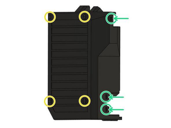
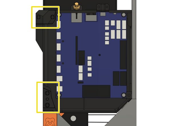
Insert 3x M3 square nuts in board_cover.
-
Insert 4x M3 hex nuts in board_cover.
-
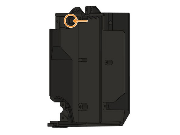
Insert one M3 square nut on the inside of the case.
-
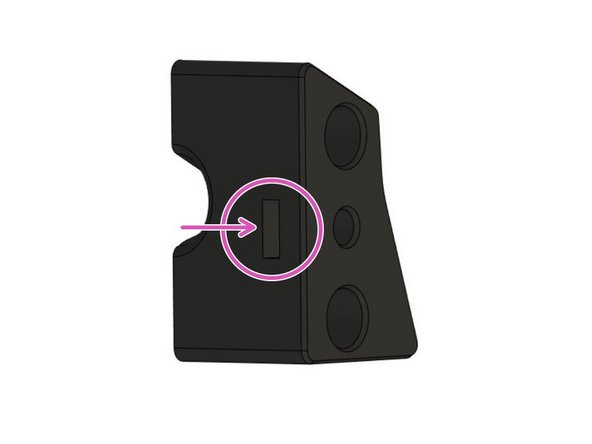
Insert one more M3 square nut in board_cable_clamp_bed.
-
Make sure to fully insert the nuts!
-
-
-
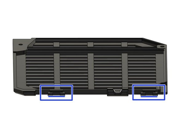
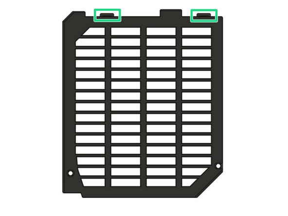
Remove both printed supports from the tabs on board_lid.
-
-
-
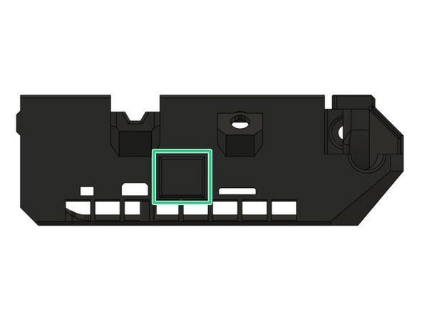
WiFi Only: If you have the WiFi version of the Duet 3 Mini 5+ you will not need to connect an Ethernet cable.
-
You can cover the cut-out for the ethernet connector with board_rj45_cap.
-
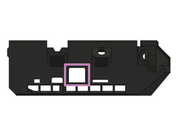
Ethernet Only: If you have the Ethernet version of the Duet 3 Mini 5+ you will need access to its Ethernet port.
-
Leave the board_rj45_cap off the case as the cut-out will allow you to attach an ethernet wire to the board.
-
-
-
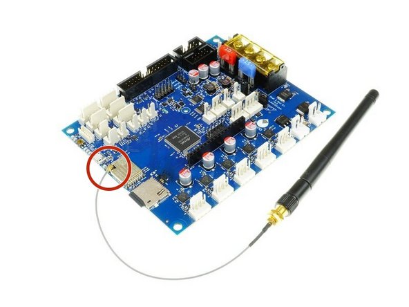
If you have the Ethernet Version of the Duet 3 Mini 5+ you can skip this step.
-
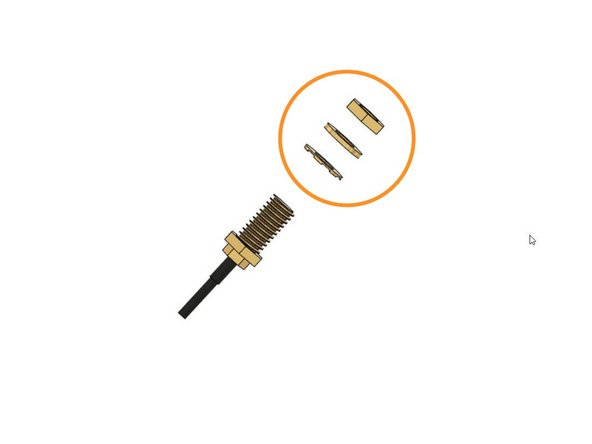
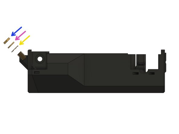
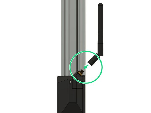
Be careful when handling the antenna, especially the connection with the board is very sensitive and you should avoid putting any strain on it.
-
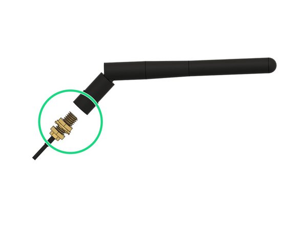
Unscrew the antenna carefully from the wire and keep it in a place where you will find it again. You can keep the antenna connected to the board.
-
Remove the nut, the washer and the locking washer from the thread as well and keep them in a place where you will find them again. They will be used to secure the antenna to the board case in a later step.
-
-
-
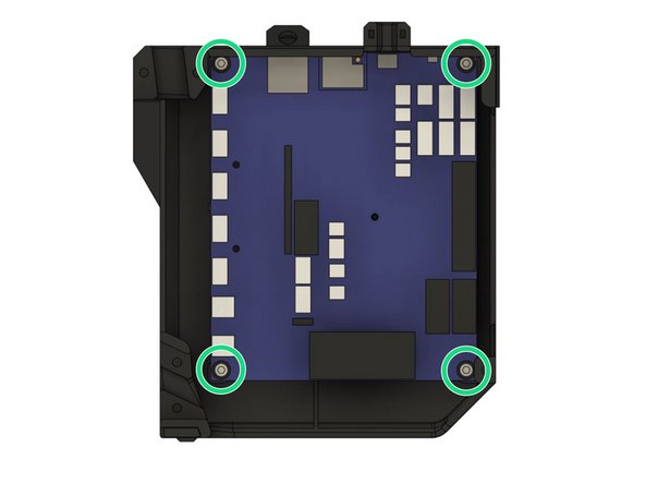
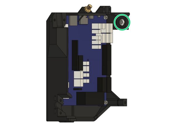
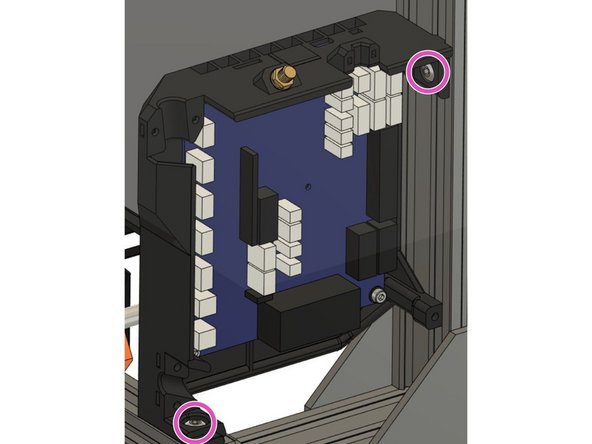
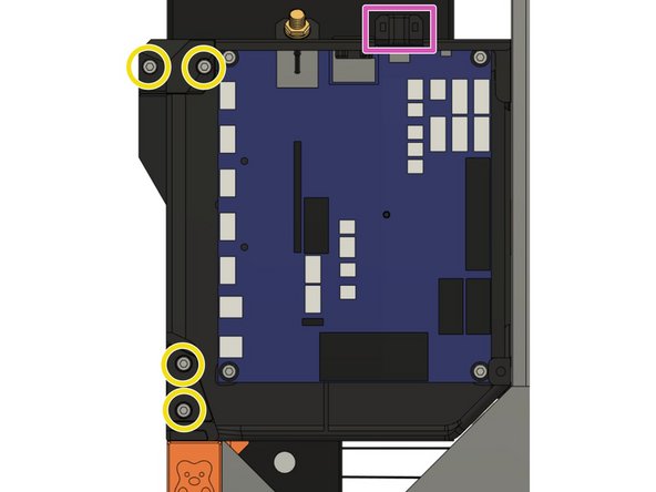
Make sure to use the printed board_washers between the screw heads and the board.
-
Secure the board in board_cover with 4x M3x10mm screws. Be careful not to over-tighten the screws as this might damage the board.
-
-
-
If you have the Ethernet version of the Duet 3 Mini 5+ you can skip this step.
-
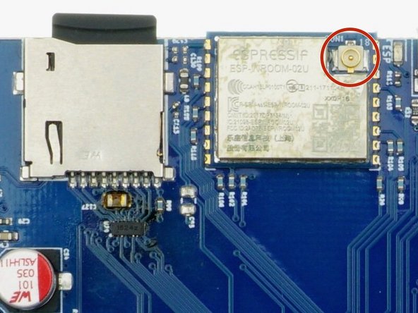
Be careful when handling the antenna, especially the connection with the board is very sensitive and you should avoid putting any strain on it.
-
The connection between antenna and the board is designed at an angle to optimize the wire position of the antenna which avoids unnecessary strain on the wire and board connection.
-
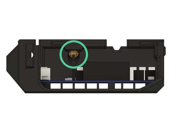
Insert the hex nut end of the antenna wire into the its pocket on the case.
-
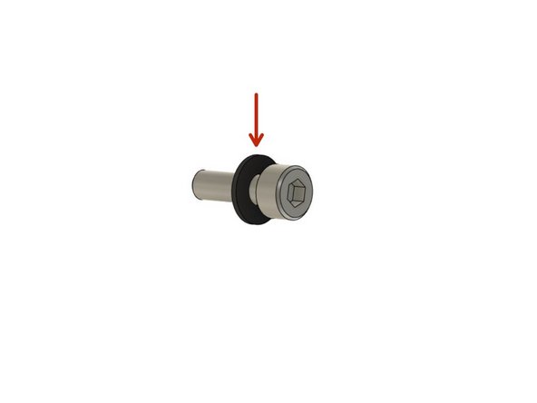
Secure the wire to the case by screwing the included nut and washers to the outside of the case until it is secured firmly. Make sure to follow the correct order:
-
Locking washer
-
Washer
-
Hex nut
-
-
-
The antenna connector is quite a tight fit, and is not intended for frequent connecting/disconnecting!
-
Carefully align the connector as square and straight as you can before firmly pushing on.
-
-
-
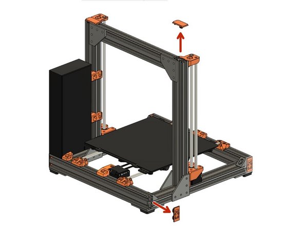
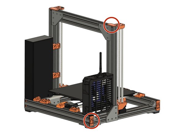
Remove the Z end cap on the left Z extrusion and on the left end of the back XY-frame extrusion (left when standing in front of the printer) .
-
-
-
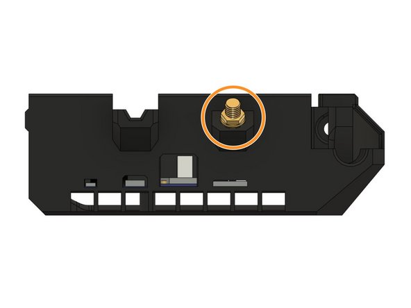
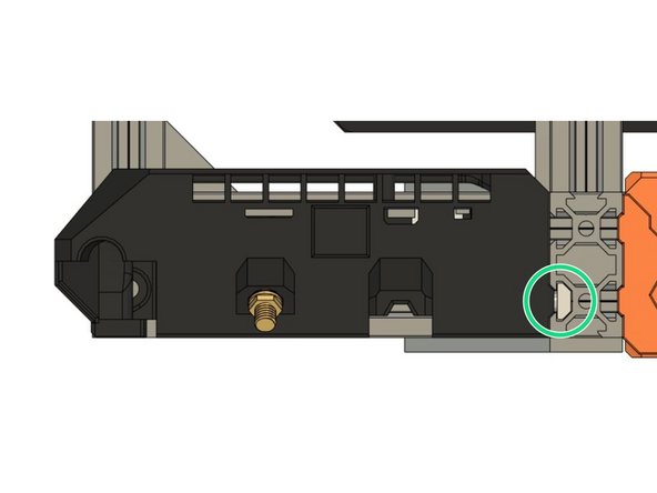
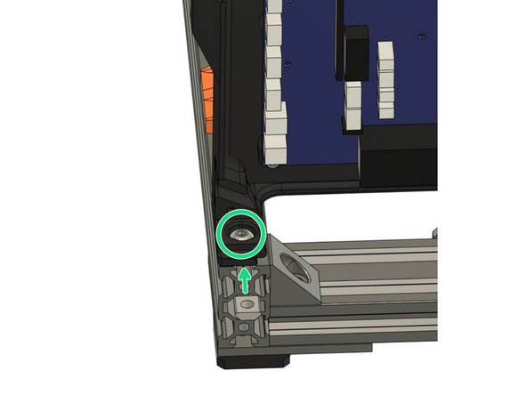
Insert a M5x8mm screw into the pocket on the top of the case. We will use this screw to secure the case to the Z extrusion on the frame.
-
Loosely thread a t-nut onto the screw from the outside of the case. Do not tighten the T-nut to the case, as we will slide the T-nut into the Z extrusion on the frame.
-
-
-
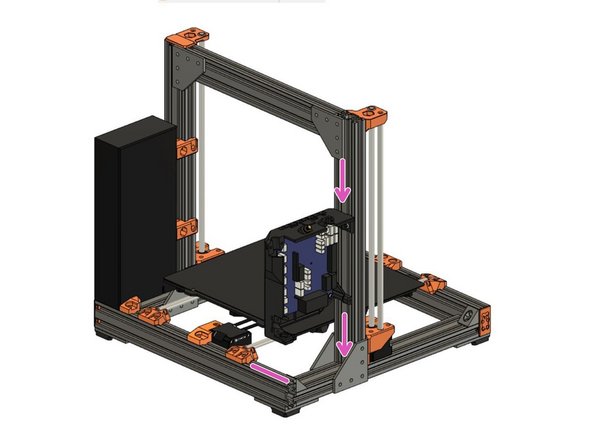
Slide the T-nut into the outside slot on the backside of the left Z extrusion.
-
Slide the case down together with the inserted T-nut.
-
Until the bottom of the case touches the top surface of the extrusion on the back of the XY-frame.
-
Do not tighten the screw yet.
-
-
-
Insert a M5x8mm screw in the pocket where the case sits on the back extrusion of the XY frame.
-
Insert a t-nut in the top slot of the extrusion and attach it to the screw we have just inserted. Do not tighten the screw yet.
-
Tighten both screws to the frame with the help of the t-nuts.
-
Tighten the case parallel to the Z extrusion.
-
-
-
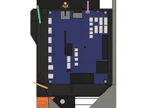
The extruder wire bundle will be entering the case on the top left opening.
-
The heated bed wire bundle will be entering the case on the bottom left opening.
-
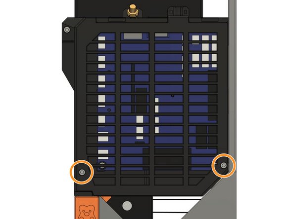
Both the extruder wire bundle and the heated bed wire bundle will be secured with the board_cable_clamp_extruder and the board_cable_clamp_bed (picture 2).
-
Secure both cable clips with 4x M3x10mm screws (picture 3).
-
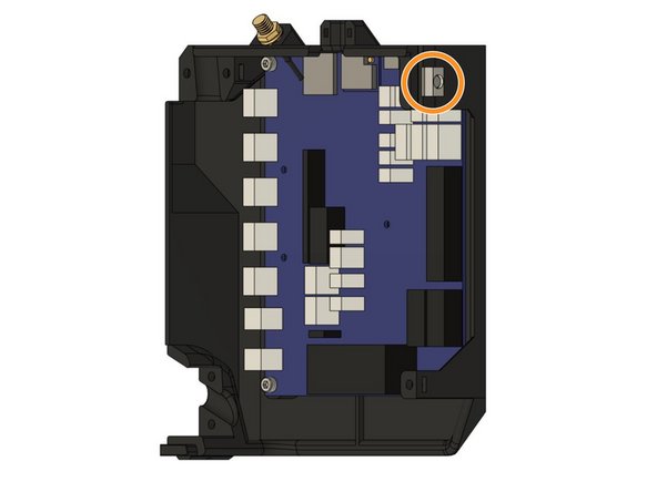
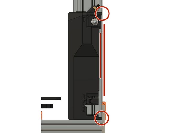
The X-axis motor wire will be entering the case on the top right opening.
-
The X-axis motor wire will be fixed with a zip tie (picture 3).
-
-
-
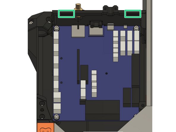
To mount the lid on the case we will insert the two tabs on the board_lid into the slots on the board_cover.
-
Then secure the lid to the case with 2x M3x10mm screws.
-
-
-
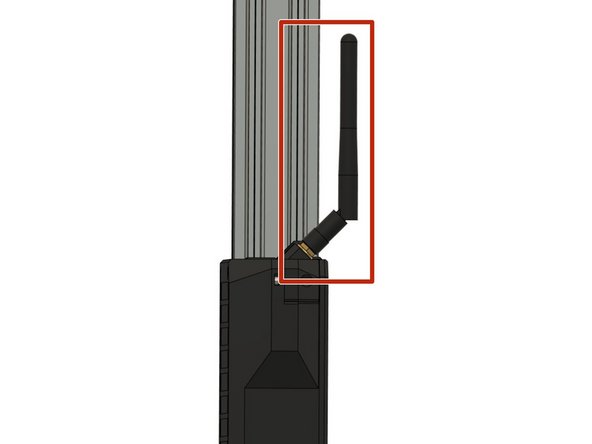
Screw the antenna on the thread sticking out of the case. Make sure it is secured firmly but do not over-tighten, not much force is needed.
-
We recommend to angle the antenna as shown in picture 2 as this will prevent it from sticking out of the frame too much. Otherwise you might damage it while working on or moving the printer later.
-
-
-
Re-attach the end caps on both the left Z extrusions and the extrusion on the back of the XY-frame.
-
-
-
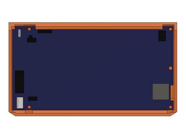
Insert the PanelDue into cover_paneldue_5in, facing down on the table.
-
Add lcd_support_left and lcd_support_right.
-
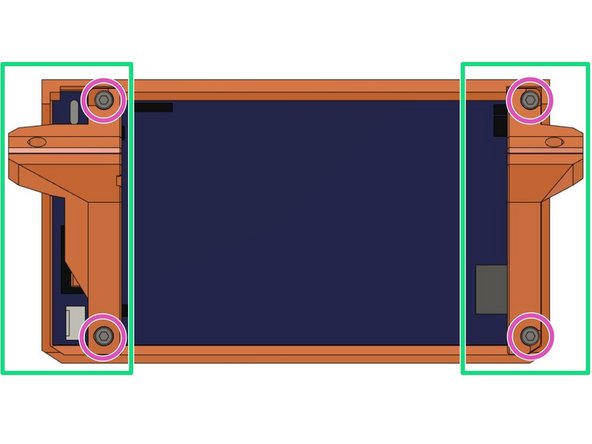
Attach the PanelDue and its supports to the case with 4x M3x10mm screws.
-
Carefully tighten the screws as over-tightening could cause damage to the PanelDue.
-
-
-
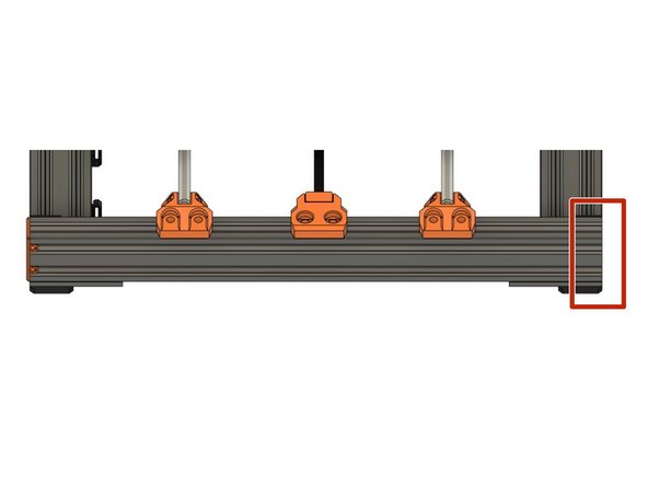
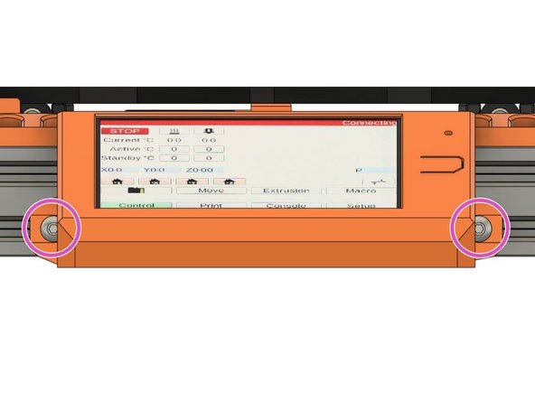
Remove one end cap on the front extrusion of the XY-frame.
-
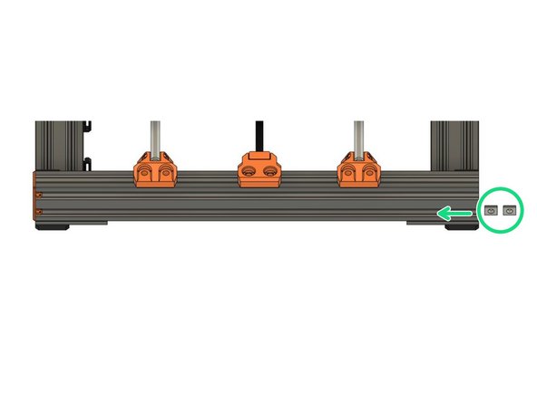
Insert two t-nuts in the bottom slot where we have removed the end cap.
-
Secure the PanelDue to the extrusion via the LCD supports with 2x M5x10mm screws.
-
-
-
You can now re-add the end cap you removed earlier.
-
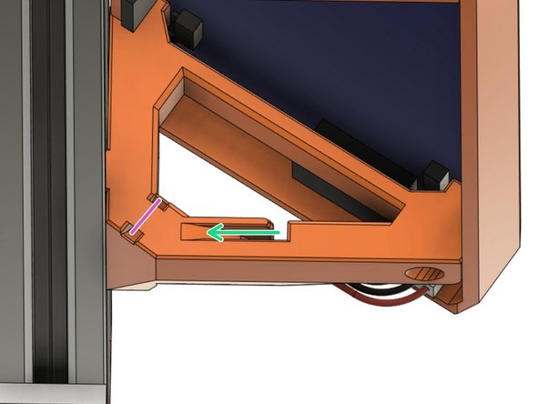
When plugging the wire into the PanelDue, you can route it through the channel in the right support.
-
Fix the wire to the support with a zip-tie. This will avid unnecessary strain on the wire/connector when moving the printer around later.
-
Be careful not to pull the zip tie too tight as this could damage the wire!
-
-
-
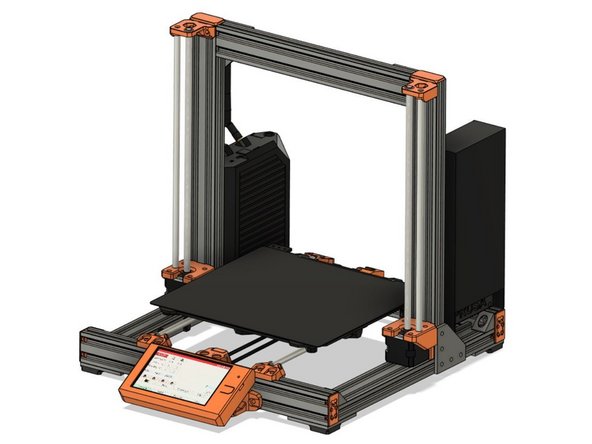
Congratulations you have assembled the necessary hardware for your Duet Bear! You can proceed to the Wiring Instructions.
-