
-
-
The Bear Extruder and X axis (X ends) are matched to each other and cannot be used separately. As a unit, they are completely compatible with stock Prusa MK2.5S, MK3S and Bear Full Upgrades
-
If you are upgrading an existing Original Prusa or clone, you need to first disassemble the x-axis and extruder. Save all the parts as some will be reused. Check the smooth rods for wear or damage. Now is a good time to replace worn rods and linear bearings, or re-lubricate if required.
-
To save time later, check all of the printed parts. Check that screw holes are clear, to allow the screws to slide in without excessive force. Once the electrical components have been added, you don’t want to be struggling with a tight screw which increases the risk of damaging a wire.
-
Disclaimer: We share these guides to make your experience as smooth as possible. However, you are responsible for your upgrade, assembly and any damage you cause to your hardware. Therefore we cannot be taken as responsible in case of damage due to the steps presented in our guides.
-
-
-
Inserting Hex Nuts: To ensure that hex nuts are properly seated, do the following:
-
Add a washer to the screw, to avoid damaging the printed part.
-
Insert the screw through the hole on the opposite side to the hexagonal cavity.
-
Thread the hex nut onto the screw and tighten the screw.
-
Ensure the hex nut is aligned with the hex cavity while tightening.
-
When the nut is fully seated, remove the screw being careful not to dislodge the nut.
-
Inserting Nyloc Nuts: You can use the same method as used for the hex nuts.
-
Inserting Square Nuts: They tend to fall out if the piece holding them is inverted. After they are inserted, check that they are properly seated by inserting a screw to engage the nut.
-
-
-
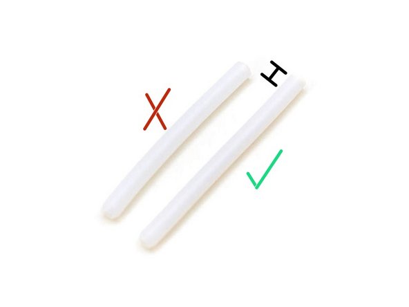
The Bear extruder uses a PTFE tube length of 50mm. It is the same PTFE tube used for MK2S, MK2.5 (non-S) and MK3 (non-S). The original Prusa MK2.5S or MK3S extruder is using a PTFE tube length of 44.2mm which will be too short for the Bear extruder.
-
If you have an undamaged 50 mm PTFE tube from a MK2S, MK2.5 (non-S) or MK3 (non-S) you can reuse it.
-
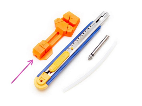
The printed parts for the extruder include a PTFE tube cutter tool that matches the specifications required for the Bear extruder. The part name is ptfe_cutter_50mm_60deg.stl
-
Follow this guide to prepare the PTFE tube Trim PTFE Tube.
-
-
-
Double check you have all parts listed on the BOM
-
It is important to check you have all the hardware before starting because there are 5 revisions of the Original Prusa extruder for MK2.5(S) and MK3(S) which have slightly different hardware.
-
-
-
Clean up strings from your printed parts with tweezers and a hot air gun (be careful).
-
Carefully check the inside of the holes in the X ends, where the smooth rods will be inserted.
-
Remove any elephant foot with a deburring tool.
-
Check all bridges. If a bridge is falling in its center: heat tweezers with a lighter and press on the area with the poor bridging, to flatten it.
-
Make sure the filament path through the extruder body is clean, round, and clear from obstructions.
-
-
-
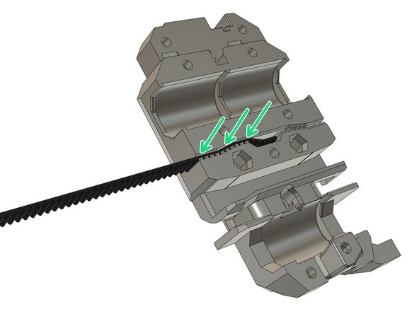
THIS STEP IS NOT OPTIONAL. If you don't do it you might be unable to finish the assembly of your Bear extruder.
-
Try to insert the belt from your original Prusa in the Bear x_carriage. Use a slotted screwdriver to make sure the belt goes fully inside. If you have trouble inserting the belt, it might be due to the following issues:
-
Your prints are over-extruded. When you print functional parts you MUST calibrate your extrusion multiplier. This is not optional, every spool is different and will melt differently. Check our calibration guide: Extrusion multiplier and filament diameter
-
You are not using a genuine Gates 2GT belt or your belt profile is not corresponding to 2GT.
-
You are using a different filament than plain PETG and the shrinkage coefficient is different. In this case, you can compensate for shrinkage within your slicer.
-
-
-
1. Unload the filament and allow the hotend to cool. Turn off the printer and remove the power plug.
-
2. Protect the printing surface and use a tray to catch small components that might fall during the disassembly.
-
3. Remove the M3x40 screw securing the Rambo/Einsy cover and disconnect all the plugs, from the board that make up the extruder cable bundle.
-
4. Cut the zip ties and remove the screws clamping the extruder cable to the Rambo/EINSY box and remove the 3mm nylon filament. Completely unwind the spiral/fabric wrap from the cables.
-
5. Cut the zip ties securing the extruder cables on the cable guide and remove the cable wrapping. Untangle the wires.
-
6. Unscrew and remove the cable guide.
-
7. Disconnect the X motor from the Rambo/Einsy. MK2.5(S) only: remove the X end stop cable from the Rambo/Einsy.
-
Be careful to not cut the cables while cutting the zip ties.
-
-
-
1. Cut the zip ties holding the extruder assembly to the linear bearings.
-
2. Remove the timing belt. Replace if worn or damaged.
-
3. Carefully remove the extruder from the X axis. Make sure you are not damaging any wires.
-
4. Tear down the entire extruder by reversing the assembly instructions provided by Prusa.
-
5. All the printed parts will be replaced. Most of the electrical parts and fasteners can be reused.
-
6. Check all wires and connectors for possible damage especially where wires may have been bend or clamped too tightly.
-
-
-
1. Remove the screws holding the z-tops in place.
-
2. Pull the z-tops off the smooth rods. Try to avoid pulling the rods out of the z-motor mounts. If a rod does come loose, avoid rotating it within the linear bearings.
-
3. MK2.5(S) only: Remove the two M2x12 screws securing the x-end limit switch.
-
4. Remove the three screws holding the x-end motor.
-
5. Pull the rods out of the x-end-motor and idler mounts taking care not to bend or twist the rods.
-
6. Remove the screws, securing the trapezoidal nuts to each x-end and spin those nuts to the top of the lead screws and remove them. They will be reused.
-
7. Lift the x-ends off the z-axis rods by lifting both the motor and idler mounts evenly.
-
-
-
Congratulations you have finished this step and are ready to start with the assembly :-)
-
Got to the next chapter: 2. X axis
-


Cancel: I did not complete this guide.
17 other people completed this guide.
