
-
-
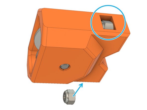
Insert an M3x18mm socket head screw in one of the x_end_idler clamp holes. This screw helps insert the hex nut.
-
Using tweezers, hold an M3 hex nut so that it can be threaded onto the M3x18mm socket head screw. Tighten that screw until the M3 hex nut is firmly seated.
-
Remove the M3x18 socket head screw and repeat on the other clamp hole.
-
-
-
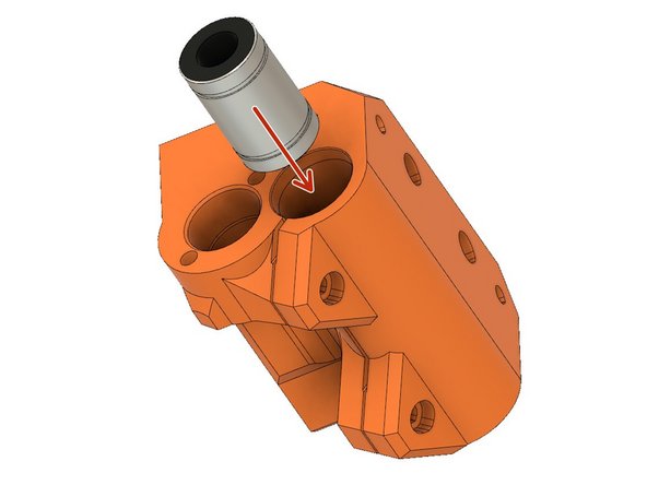
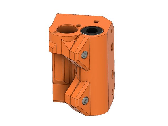
Insert an LM8UU linear bearing into the x_end_idler until it hits the internal stop.
-
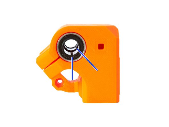
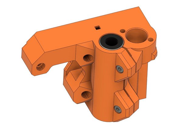
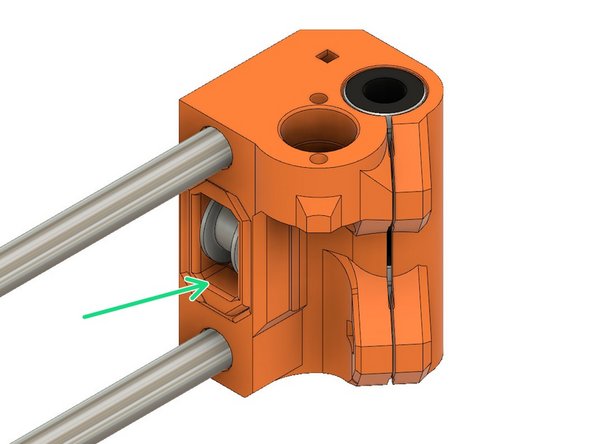
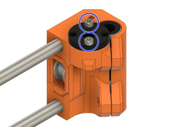
The next LM8UU linear bearing will have to be inserted so that the rows of ball bearings are at 45° to the rows in the other bearing.
-
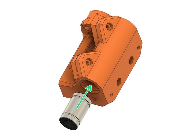
Insert that LM8UU linear bearing into the x_end_idler until it hits the internal stop.
-
Verify that the rows of balls are rotated at an angle of 45° from each other (as shown in the photograph).
-
-
-
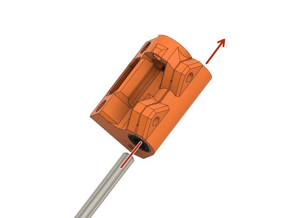
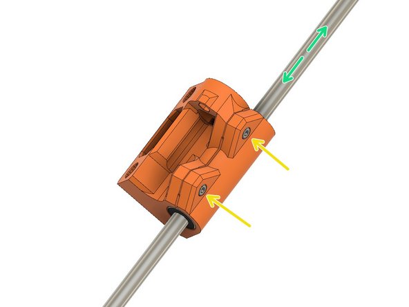
Temporarily insert a 8mm smooth rod through both LM8UU linear bearings.
-
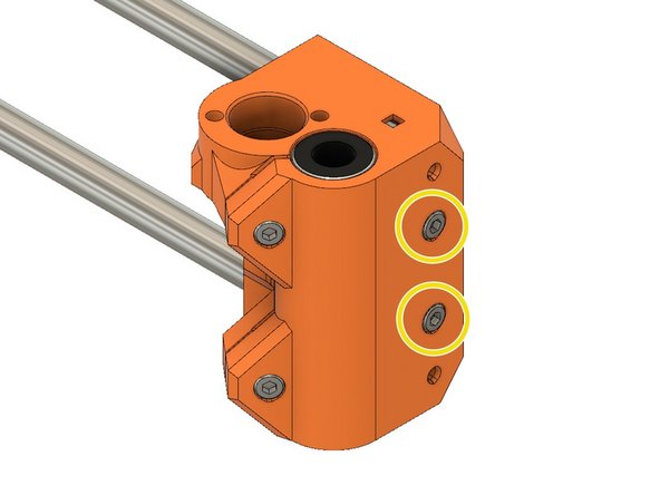
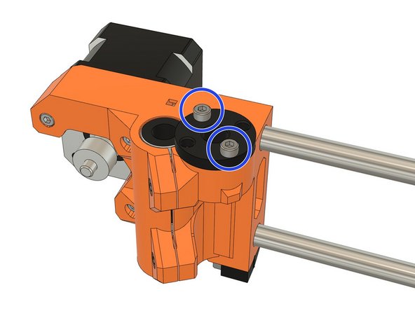
Engage two M3x10 socket head screws in the hex nuts, but do not tighten them at this time.
-
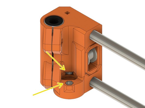
Alternatively tighten the two M3x10 clamp screws to secure the linear bearings. Slide the smooth rods back and forth while tightening.
-
Don't over-tighten the clamp screws; they need to be just tight enough to keep the bearings from moving.
-
Remove the 8mm smooth rod.
-
-
-
Repeat the 3 previous steps on x_end_motor
-
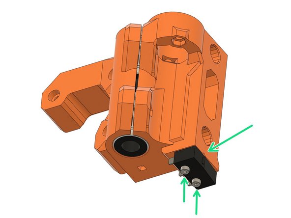
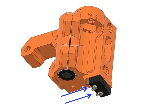
MK2(S) or MK2.5(S) only: Use two M2x12 screws to attach the x-endstop switch. Ensure the correct orientation of the switch. The microswitch should be oriented so that it is closest to the v-notch in the printed part.
-
MK2(S) or MK2.5(S) only: While tightening the screws, apply gentle pressure in the direction shown.
-
MK2(S) or MK2.5(S) only: Do not over-tighten the M2x12 screws!
-
MK2(S) or MK2.5(S) only: Double check the orientation of the endstop.
-
-
-
Check the holes for the smooth rods in the x_end_motor part and ensure that they are clean and free from obstructions.
-
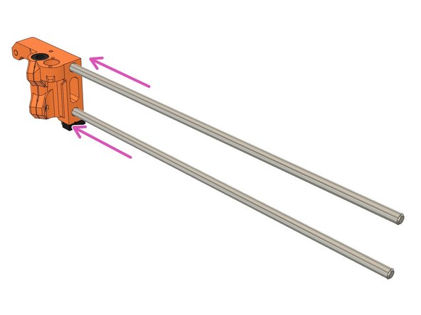
Slide the two 370mm smooth rods in the x_end_motor.
-
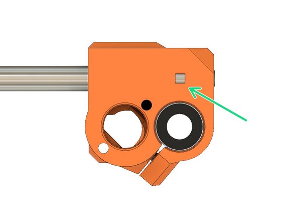
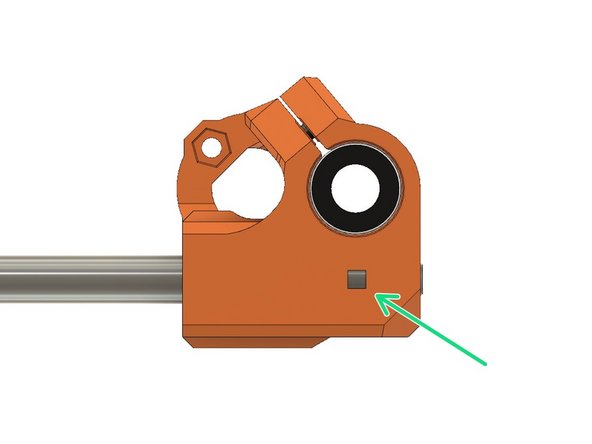
Ensure that the smooth rods are fully inserted. You can see them in the little windows on top and bottom.
-
If it is too hard to insert the smooth rods you can use a quality metal drill of 8mm and hand drill the first centimeter. Warning: don't drill the hole up to the end, only first centimeter.
-
-
-
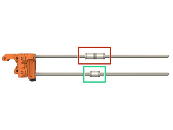
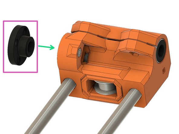
Insert two LM8UU linear bearings on the top smooth rod.
-
Insert one LM8UU linear bearing on the bottom smooth rod.
-
Be very careful inserting the LM8UU linear bearings.
-
-
-
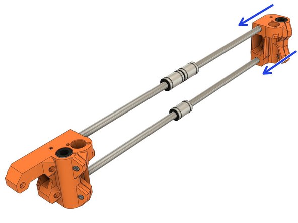
Insert both rods simultaneously into the x_end_idler and provide even pressure to force the rods all the way in.
-
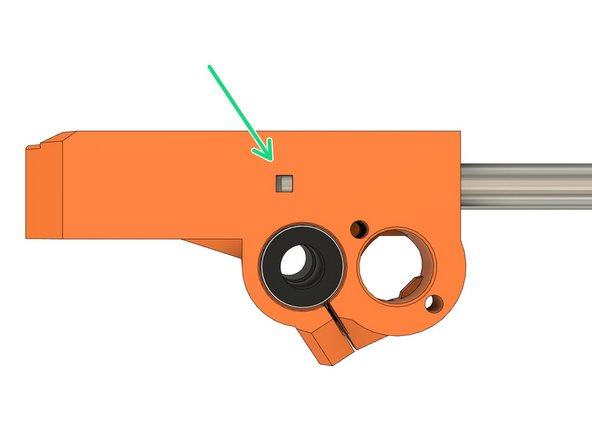
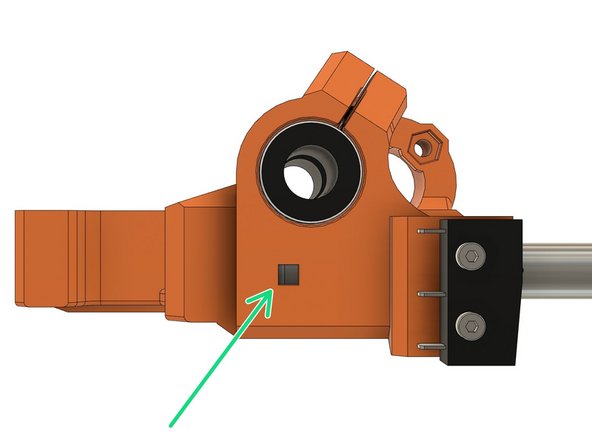
Using the observation windows, verify that each rod is fully seated.
-
Take the time to double check observation windows on both x_end_idler and x_end_motor.
-
If it is too hard to insert the smooth rods you can use a quality metal drill of 8mm and hand drill the first centimeter. Warning: don't drill the hole up to the end, only first centimeter.
-
-
-
The 2GT 16T pulley's gear teeth are not visible on the images.
-
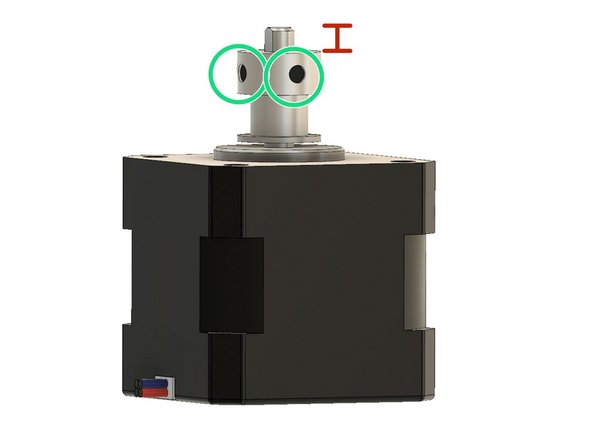
Position the 2GT 16T pulley so that approximately 3.5 to 4 mm of the shaft protrudes. Ensure the pulley is not touching the motor.
-
Align one of the set screws on the flat on the motor shaft and then tighten, alternately, each set screw until they are both snug.
-
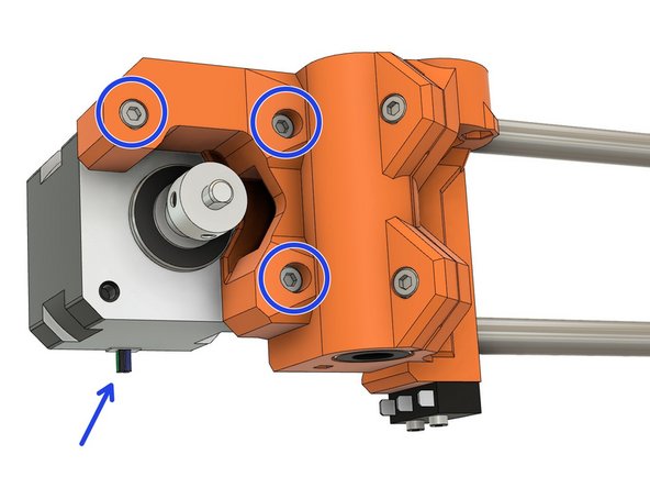
Using three M3x18 screws, attach the x-axis motor, don't fully tighten them now, we will do it in the next point. Note the orientation of the wires.
-
Finish to tighten the M3x18 screws while applying gentle pressure in the direction shown
-
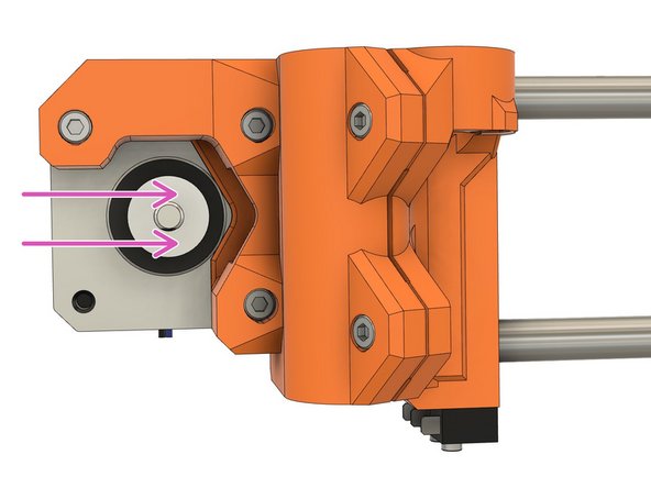
Double check the pulley position and ensure it does not touch the motor.
-
-
-
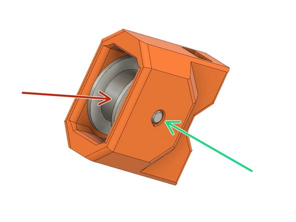
Insert the idler in the x_end_idler_tensioner.
-
Press the dowel pin through the x_end_idler_tensioner and idler bearings.
-
Verify that the dowel pin is not protruding from either side.
-
Verify that the idler spins freely.
-
Insert two M3 nylock nuts in the top and bottom of x_end_idler_tensioner. Note the orientation of the nylock nuts.
-
-
-
Insert the x_end_idler_tensioner in the x_end_idler.
-
Secure it with two M3x18 screws. Don't need to tighten the screws, only engage them.
-
-
-
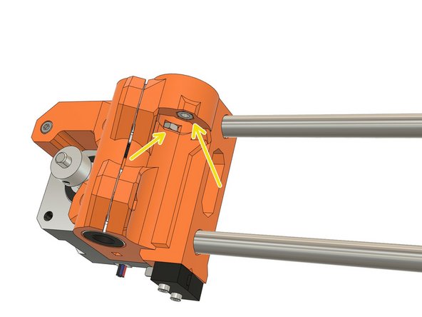
Insert two M3 hex nuts in the dedicated pockets of x_end_idler.
-
Note the orientation of the trapezoidal nut.
-
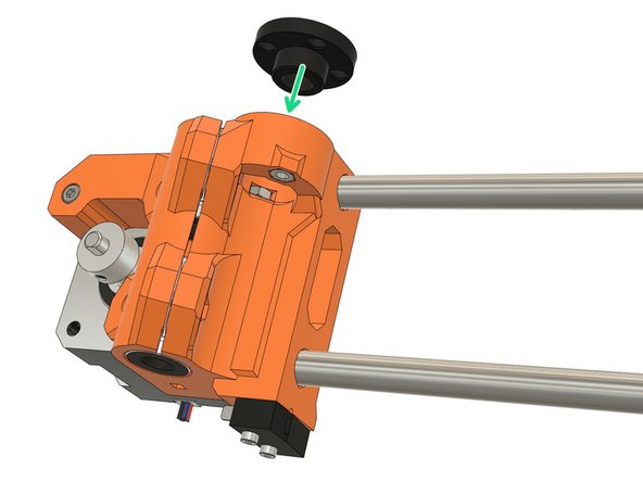
Insert a trapezoidal nut on top of x_end_idler.
-
Using two M3x18 screws, tighten the trapezoidal nut in place. Do not over-tighten the screws.
-
Verify that the trapezoidal nut is in the correct orientation.
-
-
-
Insert two M3 hex nuts into the dedicated pockets of x_end_motor.
-
Insert a trapezoidal nut on top of x_end_motor.
-
Using two M3x18 screws, tighten the trapezoidal nut in place. Do not over-tighten the screws.
-
Verify that the trapezoidal nut is in the correct orientation.
-
-
-
These steps are using the Bear Upgrade frame 2.1 as example but can be applied to Original Prusa frame and previous Bear Upgrade frame version.
-
Bear Upgrade frame only: Remove z_end_caps.
-
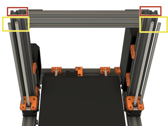
Remove the z_tops that holds the Z smooth rods.
-
Carefully slide the X axis assembly onto the Z-axis. Rotate both lead screws to engage the X axis in the trapezoidal nuts.
-
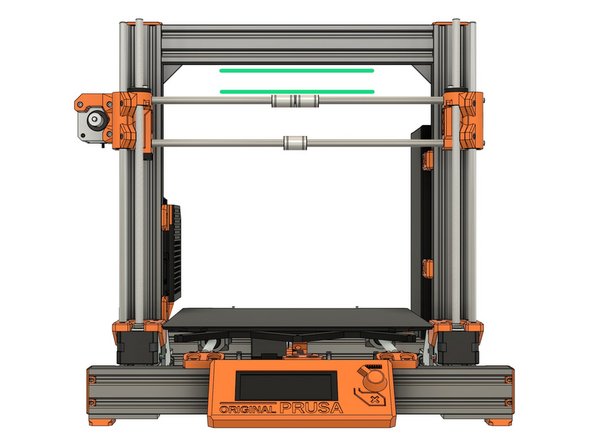
Continue to rotate both lead screws, by hand, to move the X axis assembly down by a few centimetres. If the X rods are not parallel with the top of the Z axis, rotate a lead screw on one side only, until the X axis assembly is parallel to the top of the Z axis.
-
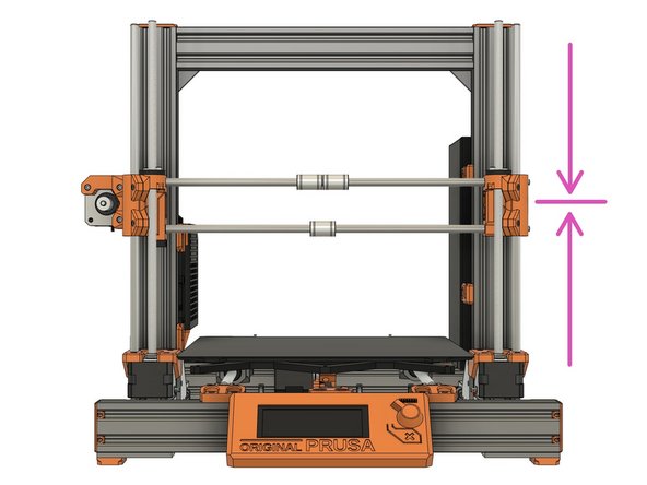
Continue to move the X axis assembly downwards until you reach the middle of the Z axis. Keep the X axis as level as possible.
-
-
-
These steps are using the Bear Upgrade frame 2.1 as example but can be applied to Original Prusa frame and previous Bear Upgrade frame version.
-
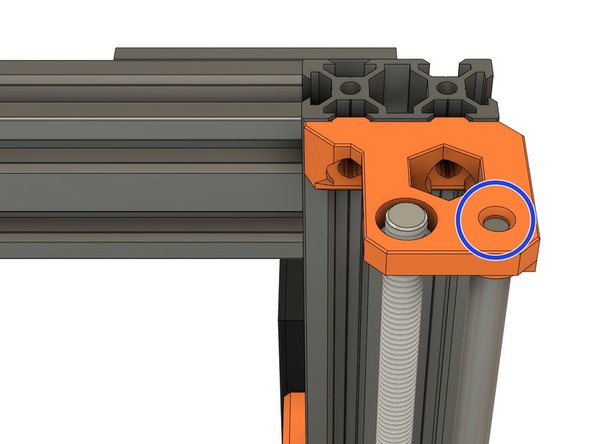
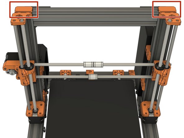
Install the Z axis tops and tighten them.
-
Bear Upgrade frame only: Make sure the z_tops are flush with the Z smooth rods on both sides
-
Bear Upgrade frame only: Tighten the z_ends_caps back in place.
-
-
-
Congratulations you have finished this chapter :-)
-
Go to the next chapter: 3. BearMera extruder
-


Cancel: I did not complete this guide.
4 other people completed this guide.
