Difficulty
Moderate
Steps
16
Time Required
- 08. LCD screen and PSU 16 steps

In Progress
This guide is currently being written. Reload periodically to see the latest changes.

Private
This guide will not appear in search results and can only be viewed by team members!
Quiz
0
-
-
Slide the lcd_support_a and lcd_support_b on the LCD control board.
-
Verify that the orientation is correct.
-
Assemble the LCD cover on the LCD control board.
-
Adjust the position of the lcd_support_a and lcd_support_b in order to insert the LCD control board on the cover.
-
The LCD control board must clip with the LCD cover.
-
Secure the LCD control board with 2x M3x10 screws (reused from your Original Prusa).
-
Put the LCD knob back in place.
-
-
-
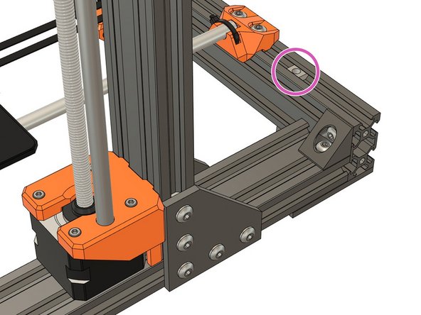
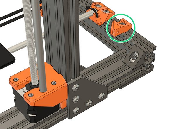
Slide 2x t-nuts in the bottom front of your frame.
-
Attach the LCD using 2x M3x10 screws.
-
-
-
We are going to test a little bit your dexterity in this step :)
-
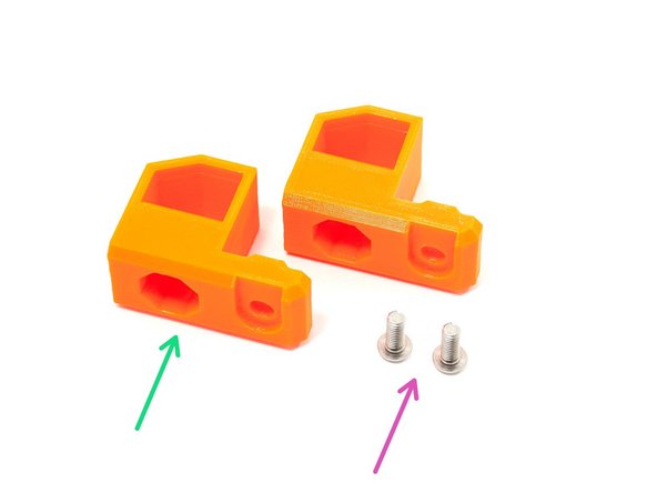
Prepare the following hardware:
-
2x M4x10 screws (reused from your Original Prusa).
-
2x psu_upper_mount.
-
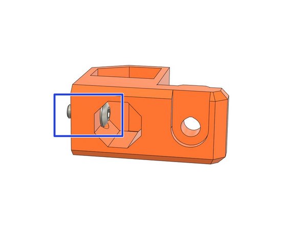
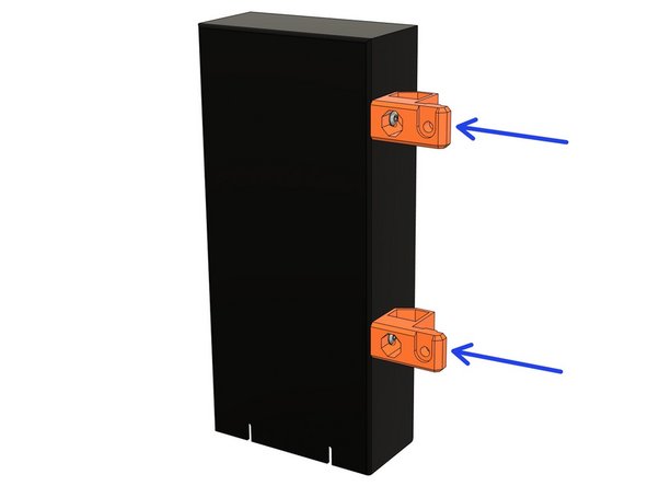
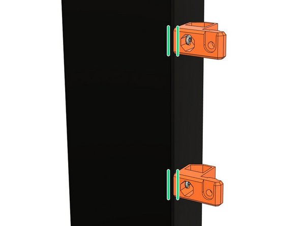
Place the M4x10 screw in the internal hole of the psu_upper_mount.
-
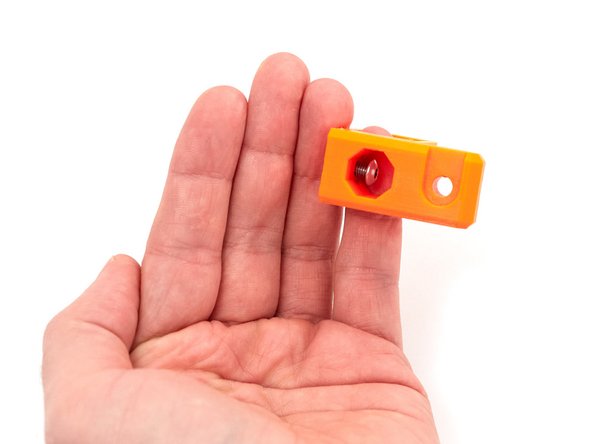
If you struggle to do it you can insert a finger in the biggest hole (check the 3rd image). Like this you can hold and guide a little the screw.
-
Insert the other M4x10 in the remaining psu_upper_mount.
-
Now try to not loose the screws until we are bolting them on the PSU :D
-
-
-
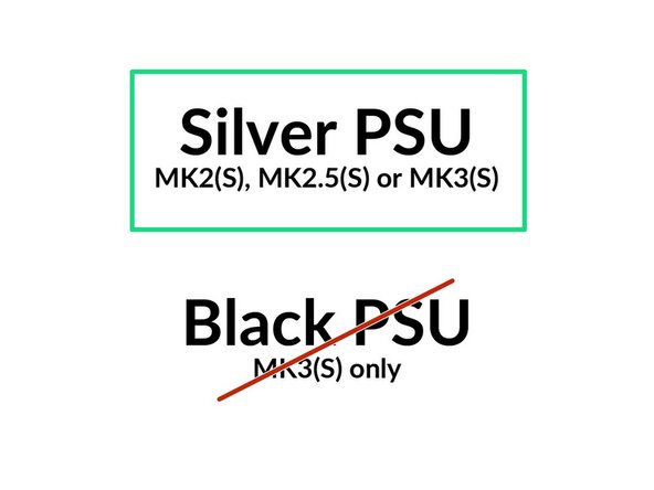
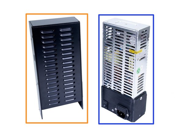
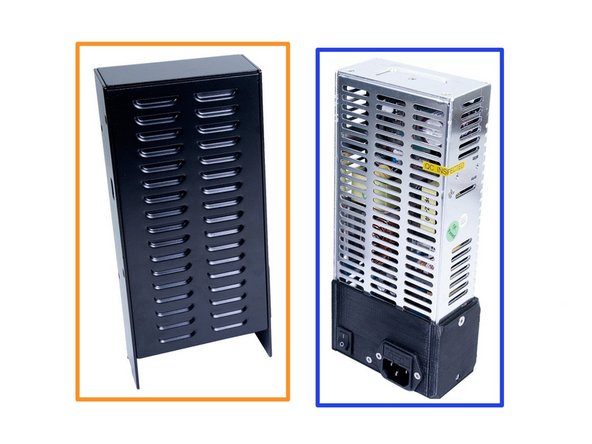
The next steps are for the Prusa silver PSU only.
-
If you have the Prusa black PSU, go to step 11
-
If you don't know which PSU you have, please check the second image.
-
Prusa black PSU
-
Prusa silver PSU
-
Image copyright: Prusa Research
-
-
-
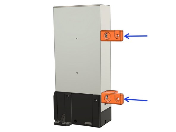
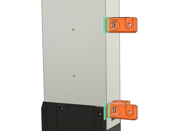
Attach the psu_upper_mounts on the silver PSU body. Tighten the M4 screws completely.
-
Verify that the psu_upper_mounts are aligned with the PSU
-
-
-
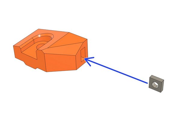
The psu_lower_mount in this step is slightly different between MK2(S)/MK2.5(S) and MK3(S) but they have the same functionality and assembly.
-
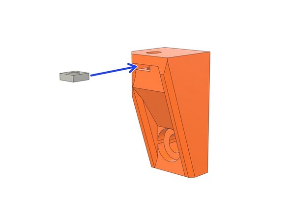
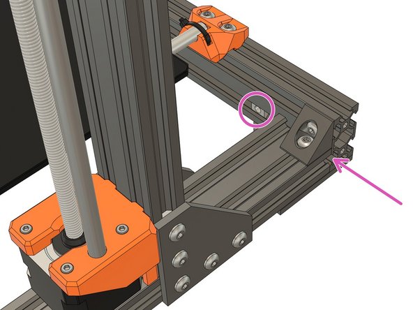
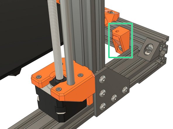
Take the psu_lower_mount and insert a square nut.
-
Slide 1x t-nut on the back extrusion from the right side of the frame.
-
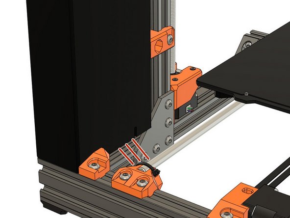
Assemble the psu_lower_mount with 1x M5x10 screw. Don't tighten fully yet as it will need some repositioning.
-
-
-
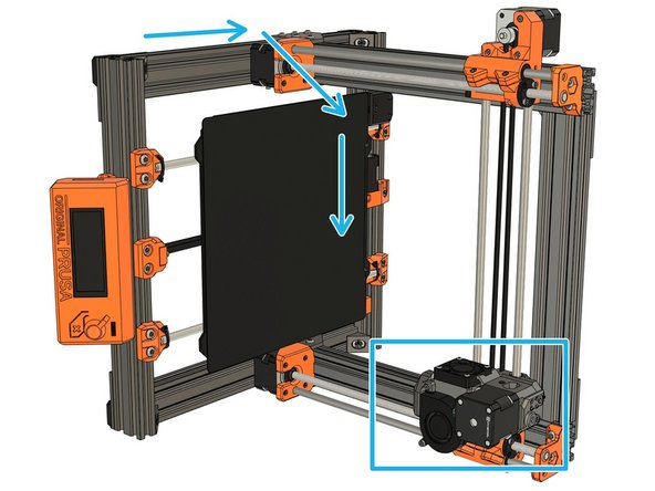
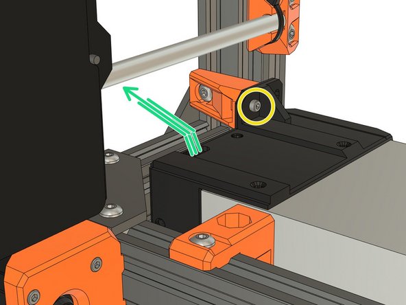
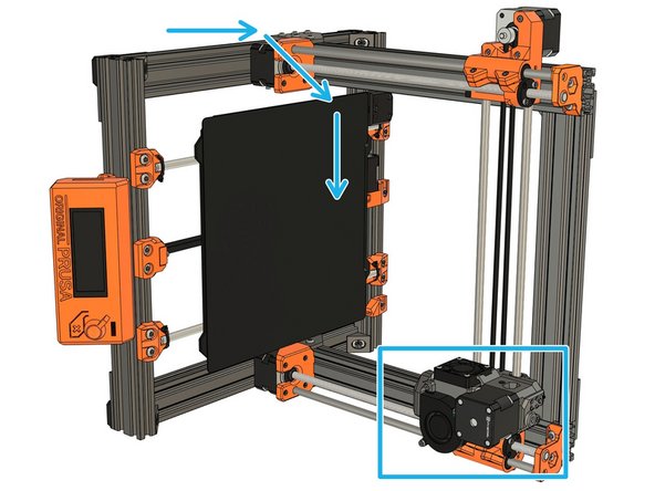
Rotate the frame to the right side. Be careful with the extruder, help him going down slowly.
-
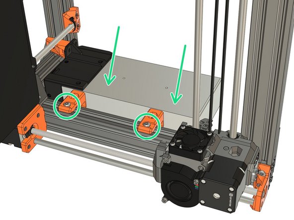
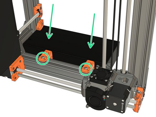
Slide 2x t-nuts from the top of the frame.
-
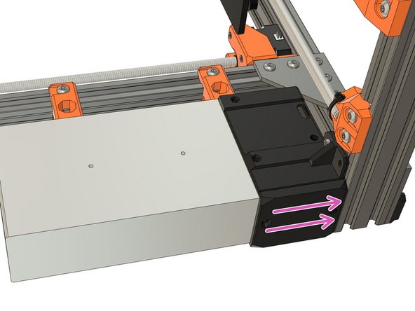
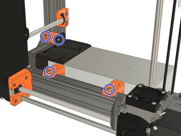
Place the PSU and secure it with 2x M5x10 screws. Do not tighten fully yet.
-
-
-
Secure the bottom of the PSU with an M3 screw reused from your Original Prusa, do not tighten fully yet. This screw has different length depending the Prusa model you have:
-
MK2(S) or MK2.5(S): length can be 18mm or 25mm (both are compatible with the psu_lower_mount).
-
MK3(S): 10mm long.
-
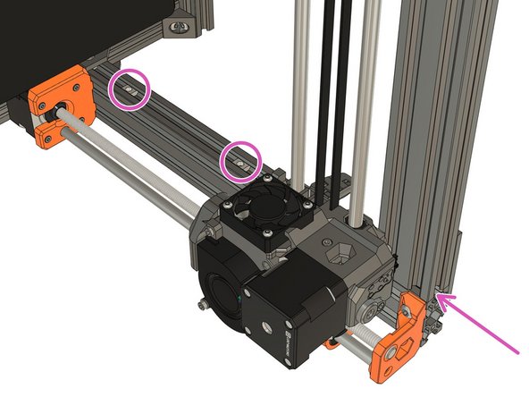
Verify that the PSU cables are not pinched and pass under the Y axis smooth rod.
-
Adjust the PSU position to be flushed with the extrusion on the back of the frame.
-
Fully tighten incrementally the screws of psu_lower_mount and psu_upper_mount.
-
Verify that the PSU cables aren't pinched and pass under the Y axis smooth rod.
-
-
-
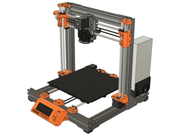
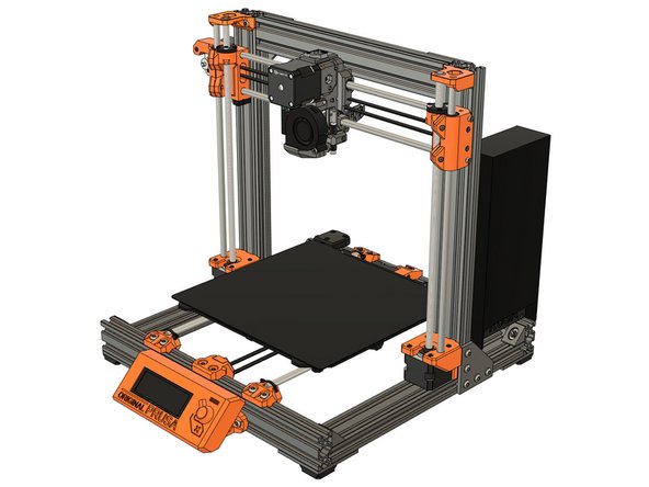
Congratulations you have finished this chapter :)
-
Go to the next chapter: 09. Electronics assembly.
-
-
-
The next steps are for the Prusa black PSU only.
-
If you have the Prusa silver PSU, go to step 5
-
If you don't know which PSU you have, please check the second image.
-
Prusa black PSU
-
Prusa silver PSU
-
Image copyright: Prusa Research
-
-
-
Attach the psu_upper_mounts on the silver PSU body. Tighten the M4 screws completely.
-
Verify that the psu_upper_mounts are aligned with the PSU
-
-
-
Take the psu_lower_mount and insert a square nut.
-
Slide 1x t-nut on the back extrusion from the right side of the frame.
-
Assemble the psu_lower_mount with 1x M5x10 screw. Don't tighten fully yet as it will need some repositioning.
-
-
-
Rotate the frame to the right side. Be careful with the extruder, help him going down slowly.
-
Slide 2x t-nuts from the top of the frame.
-
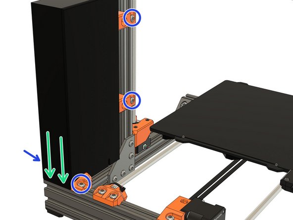
Place the PSU and secure it with 2x M5x10 screws. Do not tighten fully yet.
-
-
-
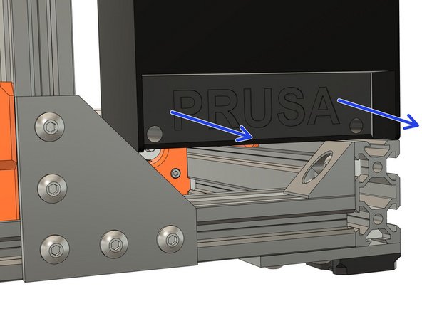
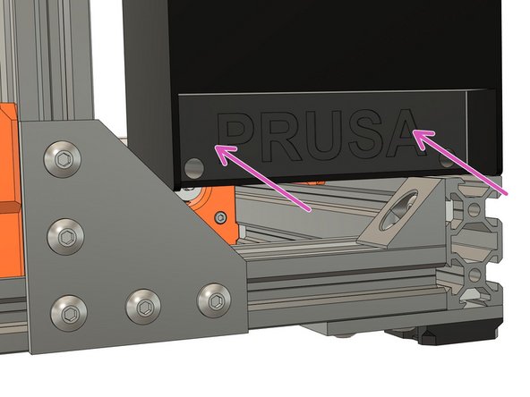
Remove the PSU cover (with Prusa logo) by unscrewing the 2x M3x10 screws.
-
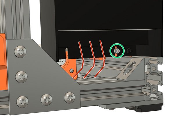
Take an extra M3x10 (reused from your Original Prusa) screw and secure the PSU to the psu_lower_mount. Do not tighten fully yet.
-
Verify that the PSU cables are not pinched, goes out of the back of the PSU and pass under the Y axis smooth rod.
-
Verify that the PSU cables are not pinched and routed correctly.
-
-
-
Adjust the PSU position to be flushed with the extrusion on the back of the frame.
-
Fully tighten incrementally the screws of psu_lower_mount and psu_upper_mount.
-
Reassemble the PSU cover with 2x M3x10 screws (reused from your Original Prusa).
-
Verify again that PSU cables aren't pinched and correctly routed.
-
-
-
Congratulations you have finished this chapter :)
-
Go to the next chapter: 09. Electronics assembly.
-