
-
-
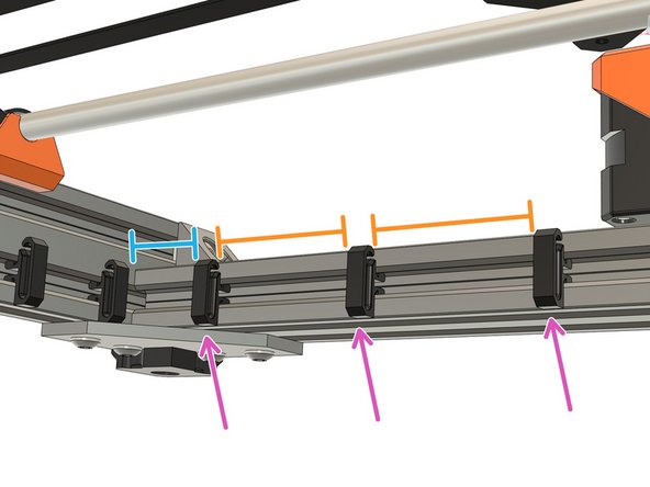
In the next steps we will install cable clips. You have to put them in the groove of an extrusion and rotate them 90° as shown in these images.
-
There are 3 different types of cable clip but they are all installed in the same way.
-
Some images in this chapter are taken from the original Prusa assembly guide and are copyright of Prusa Research (steps 23, 28, 33 and 34).
-
-
-
Prepare the following printed parts:
-
5x cable_clip_lcd
-
6x cable_clip_vertical
-
2x cable_clip_horizontal
-
-
-
The placement of the cable clips doesn't need to be particularly precise.
-
Install 2x cable_clip_lcd on the front extrusion with the following distances:
-
30mm
-
10mm
-
Install the 3 remaining cable_clip_lcd on the side with the following distances:
-
30mm
-
50mm
-
-
-
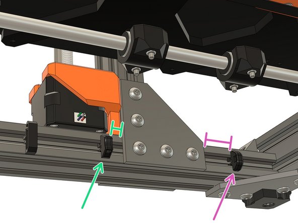
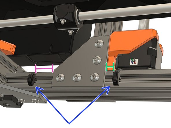
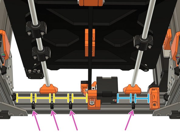
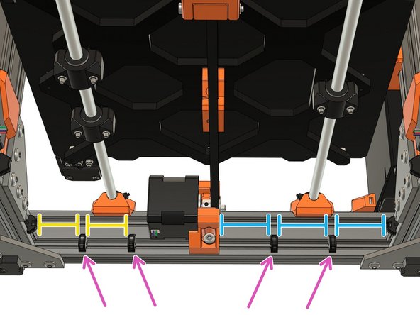
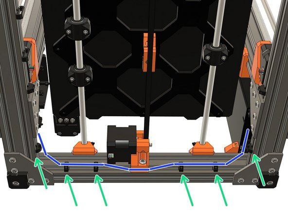
Install 1x cable_clip_vertical under the left Z motor at 10mm from the joining plate.
-
Install 1x cable_clip_horizontal, 25mm from the other side of the joining plate.
-
Repeat this step for the right Z motor, with the same distances.
-
-
-
-
-
-
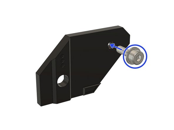
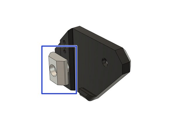
Take the rambo_base_lower_mount and insert an M3x10 scew with a washer through the smallest hole.
-
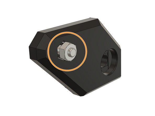
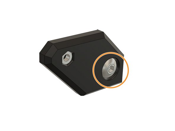
From the other side, thread on an M3 hex nut and tighten the screw until the nut is fully seated in the part .
-
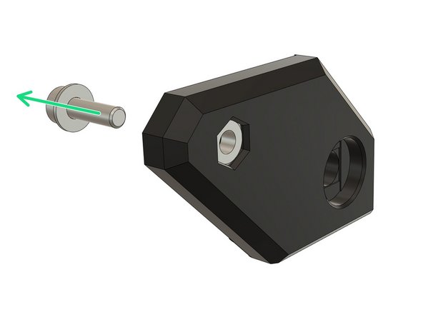
Remove the screw and washer.
-
-
-
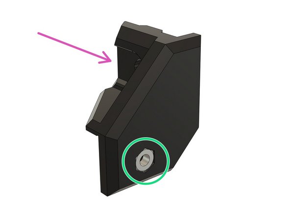
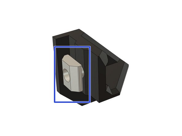
Insert 1x M5x8 screw into the rambo_base_lower_mount.
-
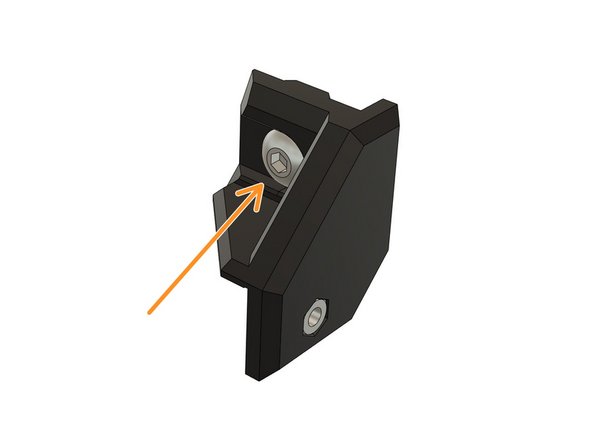
Thread 1x t-nut onto the M5 screw (1-2 turns) and orient it vertically.
-
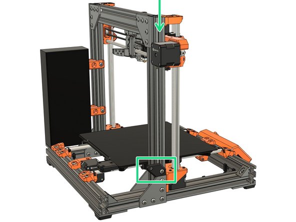
Slide the rambo_base_lower_mount into the outside channel of the extrusion (X motor side) and down to the joining plate. Make sure that the rambo_base_lower_mount is flush with the joining plate, then fully tighten the M5 screw.
-
-
-
Take the rambo_base_upper_mount.
-
Insert an M3 hex nut, into the part, using the same technique used for the rambo_base_lower_mount.
-
Insert 1x M5x8 screw into the rambo_base_upper_mount.
-
Thread 1x t-nut onto the M5 screw (1-2 turns) and orient it vertically.
-
-
-
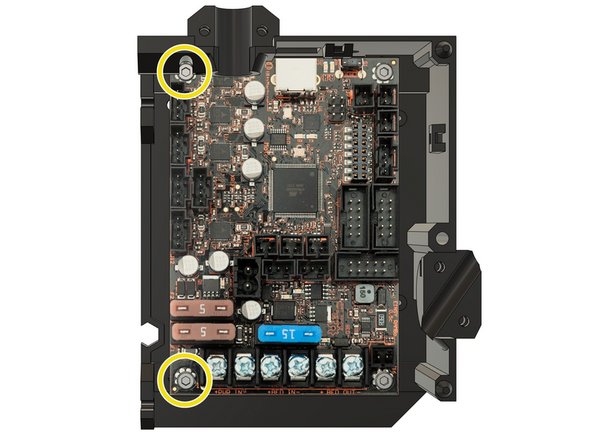
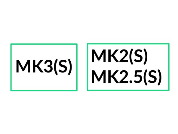
In this step we are showing a RAMBo Einsy board (MK3(S)) but the step is the same for the RAMBo Mini board (MK2(S) and MK2.5S(S)).
-
Remove the two M3x10 screws from the left side of the board.
-
Remove the 2x hex nuts from the back of the electronic cover. You can thread a screw into the nuts to pull them out.
-
-
-
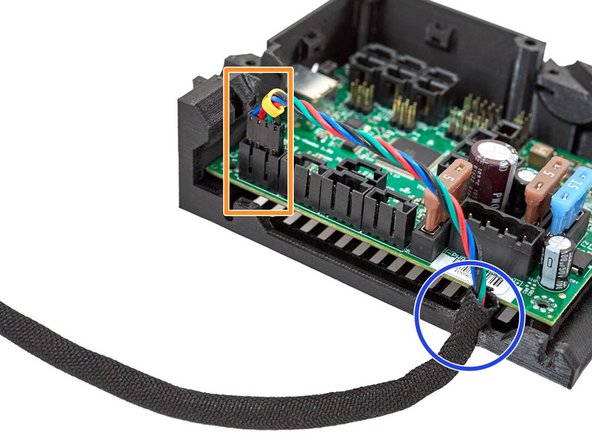
Take the X axis motor and plug it into the top left connector (X motor) (4 pins).
-
This is the same for the MK2(S), MK2.5(S) and MK3(S).
-
Push the textile sleeve and cable into the hexagonal hole, as shown. Allow some slack in the cable, so as not to put any strain on the connector.
-
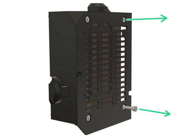
Insert 2x M3x14 screws. Take care that they do not fall out while you are attaching the cover to the mounts.
-
Attach the electronics cover to the rambo_base_lower_mount by fully tightening the lower M3x14 screw.
-
-
-
Slide the rambo_base_upper_mount into the outside channel of the extrusion (X motor side).
-
Align the rambo_base_upper_mount with the mounting point of the electronics cover and fully tighten the upper M3x14 screw.
-
Fully tighten the M5x8 screw.
-
-
-
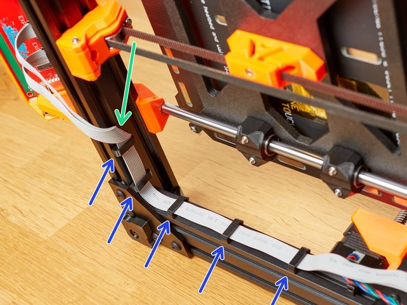
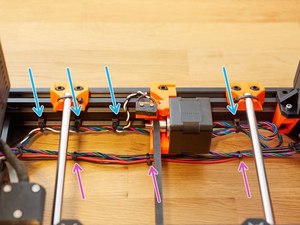
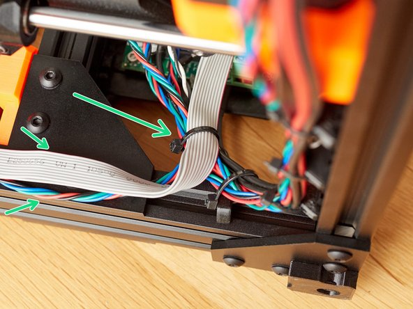
Create a twisted loop with the LCD cables under the front of the frame. Don't pinch the cables!
-
Clip the LCD cables into the cable_clip_lcd.
-
Insert a zip tie and place the left Z motor cable over the cable_clip_vertical.
-
Attach the LCD cables and Z motor cable to the cable_clip_vertical using the zip tie. Take care not to over-tighten the zip tie and pinch the LCD cables.
-
-
-
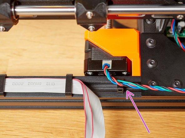
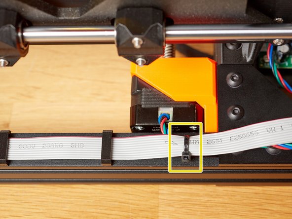
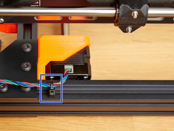
Attach the right Z motor wire to the cable_clip_vertical, with a zip tie, as shown.
-
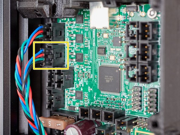
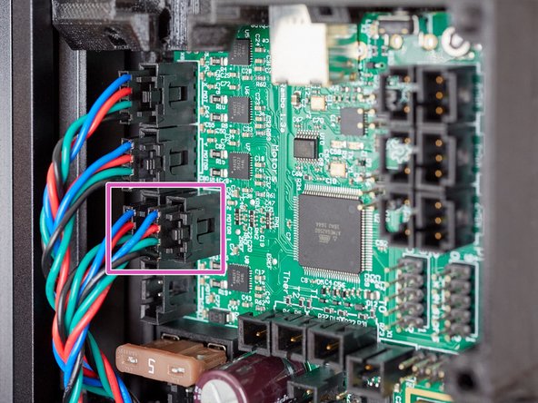
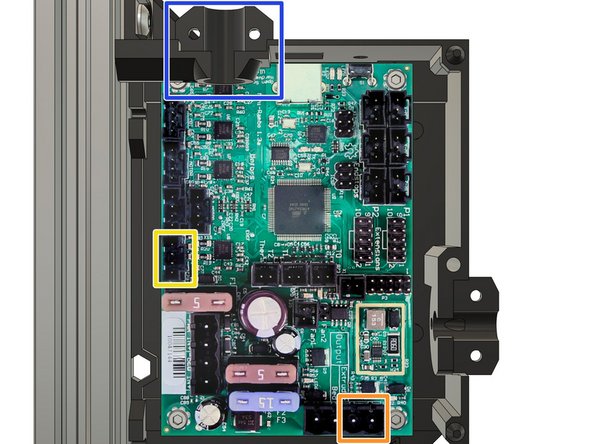
Plug the Y axis motor into the correct connector on RAMBo Mini/Einsy board, as shown.
-
Plug the two Z motors into correct connectors on the RAMBo Mini/Einsy board, as shown. The order, (Left or Right) that the Z motors are plugged into the board, does not matter.
-
Verify that the connections are fully inserted and are plugged into the correct connectors.
-
-
-
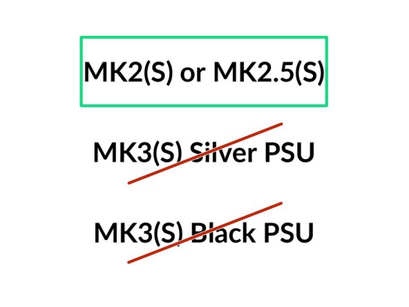
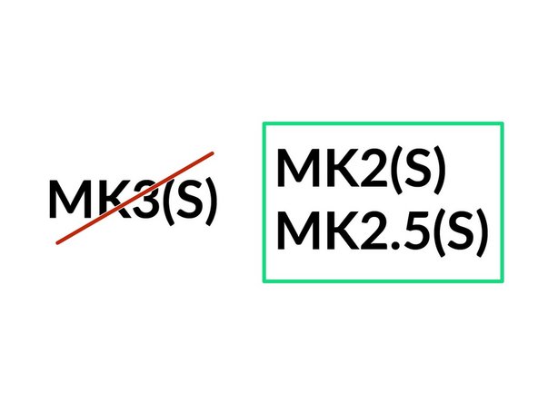
The next steps are for the MK2(S) or MK2.5(S) only.
-
If you have a MK3(S) jump to step 26.
-
-
-
The next steps will not cover every detail of the wiring, only those specific to the Bear frame upgrade. If you are unsure of how to proceed with the wiring, not covered by this guide, please consult the original Prusa assembly guides:
-
-
-
-
Be extremely careful and take your time with the wiring. Incorrect wiring may pose a risk of damaging the printer, or worse.
-
-
-
Direct links to the original Prusa electronics assembly guides: MK2(S), MK2.5, MK2.5S
-
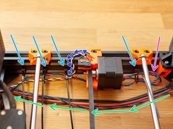
Gather together PSU cables with the right Z motor (on the PSU side). Those cables are too short to be rooted to the back on MK2(S)/MK2.5(S).
-
Create an S with the Y end stop cable to avoid straining this wire.
-
The Y motor cable is a little too long. To help with the wiring you can create a small loop with the excess length.
-
Gather the Y motor cable and Y end stop cable and add 4 zip ties to group the cables as shown in the image. Do not tighten the zip ties yet as you may need to readjust the position of some cables.
-
Make sure no wire is under tension. Do not over-tighten the zip ties or you could damage the wires.
-
-
-
-
Direct links to the original Prusa electronics assembly guides: MK2(S), MK2.5, MK2.5S
-
Insert the heated bed wiring and textile sleeve (or spiral wrap) through the right of the electronics cover. Secure them with the printed part and 2x M3x10 screws.
-
The image is showing the electronic cover for MK2.5(S), the MK2(S) version is slightly different. Refer to the Prusa guide if necessary.
-
Plug the following connectors:
-
Heated bed thermistor.
-
Heated bed heater.
-
Check that all connectors are properly plugged in and no wire is under tension or pinched!
-
-
-
Do not over-tighten the zip ties as you might damage the wires.
-
You can now improve the placements of the cables running along the back of the frame and carefully tighten the zip ties.
-
Add 3 zip ties to the PSU and right Z motor mount cables. Carefully tighten them.
-
With a zip tie, bundle all the cables, including the LCD cables and the left Z motor (from the electronic cover), together.
-
-
-
Direct links to the original Prusa electronics assembly guides: MK2(S), MK2.5, MK2.5S
-
Insert the extruder wiring and textile sleeve (or spiral wrap) through the top of the electronics cover. Secure them with the printed part and 2x M3x10 screws.
-
The image is showing the electronic cover for MK2.5(S), the MK2(S) version is slightly different. Refer to the Prusa guide if necessary.
-
Plug the following connectors:
-
Extruder motor
-
Extruder heater
-
Check that all connectors are properly plugged in and no wire is under tension or pinched!
-
-
-
Direct links to the original Prusa electronics assembly guides: MK2(S), MK2.5, MK2.5S
-
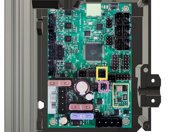
We are now going to connect the PINDA, left hotend fan and filament sensor. This steps is slightly different for the MK2(S) and the MK2.5(S). The 1st image shows MK2(S) connections and the 2nd and 3rd images show MK2.5(S) connections (via adapters).
-
Plug the following connectors:
-
Left hotend fan
-
PINDA probe
-
Filament sensor for MK2.5(S) only. Use the lower row and ensure the red wire is oriented toward the back of the printer (check the 3rd image).
-
Check that all connectors are properly plugged in and no wire is under tension or pinched!
-
-
-
Direct links to the original Prusa electronics assembly guides: MK2(S), MK2.5, MK2.5S
-
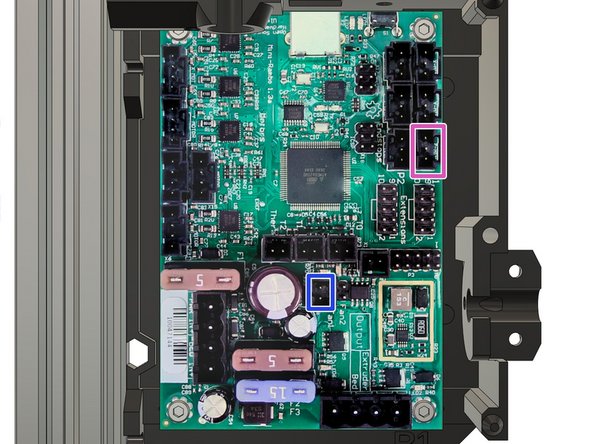
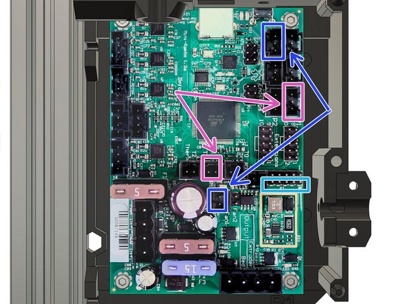
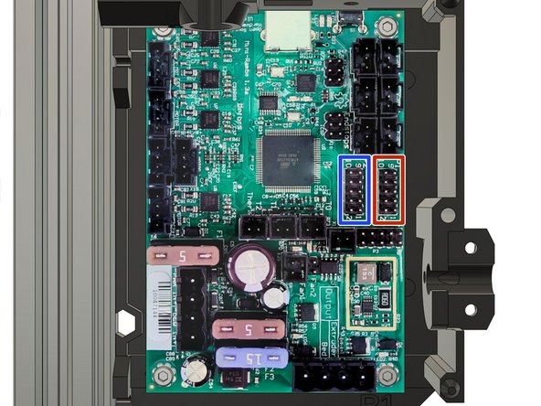
Plug the following connectors:
-
Extruder thermistor (has yellow and green heat shrink).
-
Front extruder fan (has a red heat shrink). The red wire must face up, on the side of the extruder's thermistor.
-
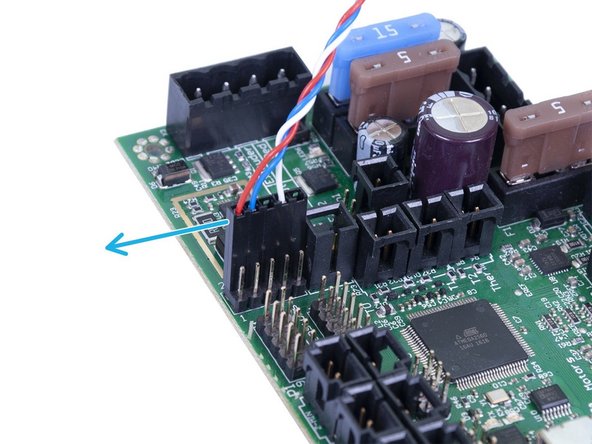
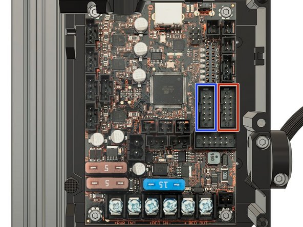
LCD cable with TWO stripes (named EXP2 on the LCD board)
-
LCD cable with ONE stripe (named EXP1 on the LCD board)
-
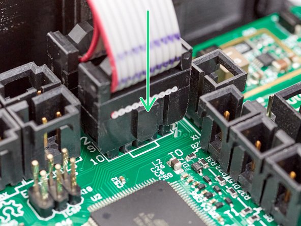
Check the orientation of the LCD cables. The locator tab, on the connector, should match the white drawing on the RAMBo Mini board. Typically this means that the red stripe on the ribbon cable is towards the top of the board, as shown.
-
Check that all connectors are properly plugged in and no wire is under tension or pinched!
-
-
-
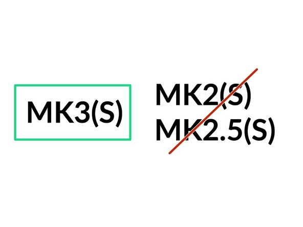
The next steps are for the MK3(S) only.
-
If you have a MK2(S) or MK2.5(S) jump to step 17.
-
-
-
The next steps will not cover every detail of the wiring, only those specific to the Bear frame upgrade. If you are unsure of how to proceed with the wiring, not covered by this guide, please consult the original Prusa assembly guides:
-
MK3 (B3/R2 design), early version of the electronics cover.
-
MK3 (B7/R3 design), the electronics cover has a removable part for the RPi Zero W
-
-
Be extremely careful and take your time with the wiring. Incorrect wiring may pose a risk of damaging the printer, or worse.
-
-
-
Direct links to the original Prusa electronics assembly guides: MK3 (B3/R2 design), MK3 (B7/R3 design), MK3S.
-
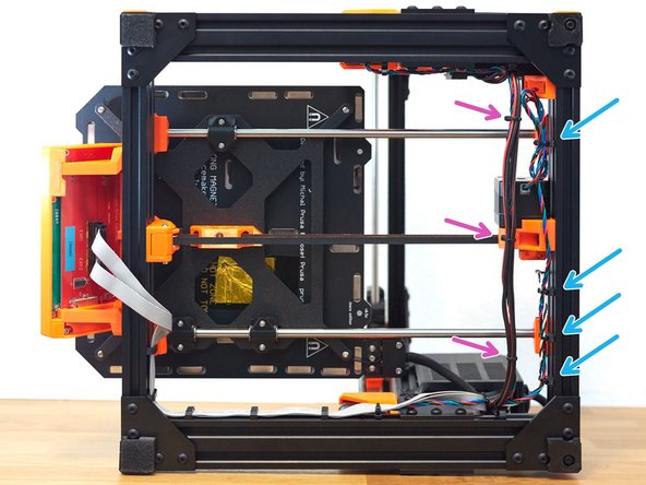
Gather the cables from the PSU (including Power Panic), the Y motor, and the Z motor from the PSU side (do not include the Z motor cable from the X motor side).
-
Add zip ties to group the cables as shown on the image. Do not tighten the zip ties yet as you may need to adjust the position of some cables later.
-
Verify that no wire is under tension.
-
-
-
Direct links to the original Prusa electronics assembly guides: MK3 (B3/R2 design), MK3 (B7/R3 design), MK3S.
-
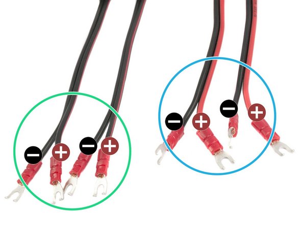
There are two versions of the PSU wires, make sure you identify which are the positive and the negative wires. This is extremely IMPORTANT.
-
Both wires on each pair are black, the POSITIVE WIRE is marked with a RED LINE along its length.
-
For each pair there is a red and a black wire. The POSITIVE WIRE is FULLY RED (you might still see a little black line).
-
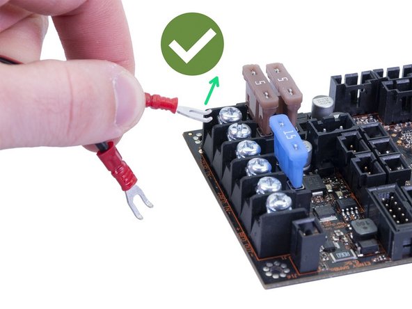
The wire terminals must be oriented correctly when you connect them to the board. The 2nd image shows the CORRECT orientation. The 3rd image shows the wrong orientation.
-
-
-
Direct links to the original Prusa electronics assembly guides: MK3 (B3/R2 design), MK3 (B7/R3 design), MK3S.
-
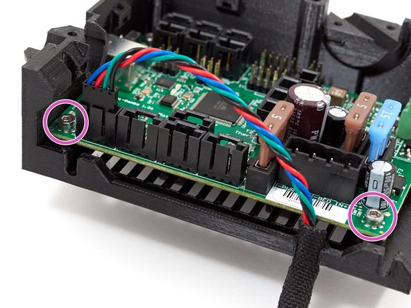
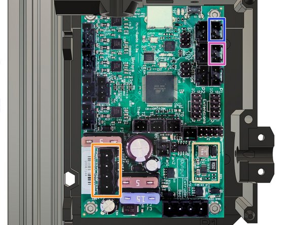
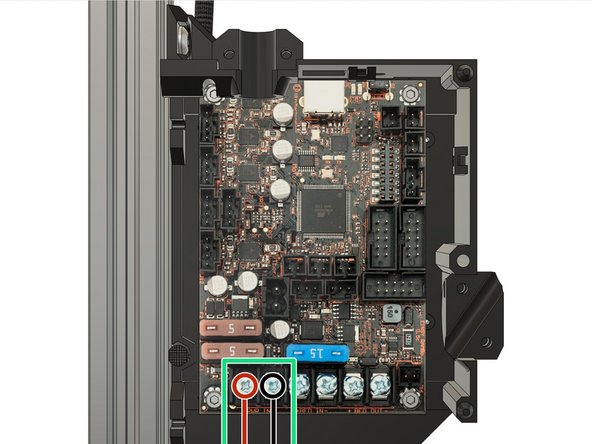
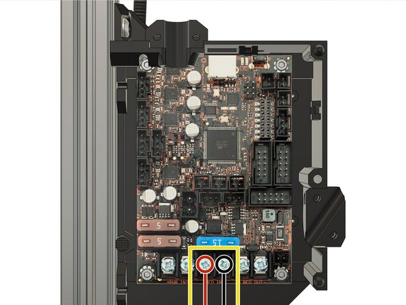
Using a Philips screwdriver, connect the 1st pair of wires from the PSU:
-
Positive, red wire, connects to the screw terminal indicated by the red circle in the image
-
Negative, black wire, connects to the screw terminal indicated by the black circle in the image.
-
Tighten the screws firmly.
-
Double check that you have connected the wires in the correct order and orientation. Note that the wire terminal should go under the washer of the screw terminal.
-
-
-
Direct links to the original Prusa electronics assembly guides: MK3 (B3/R2 design), MK3 (B7/R3 design), MK3S.
-
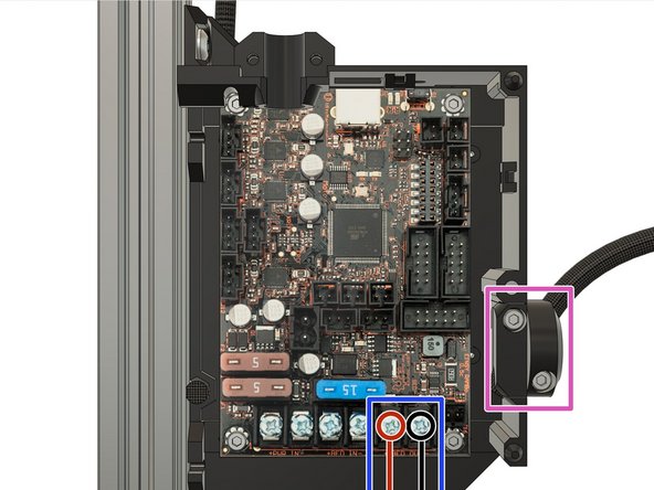
Using a Philips screwdriver, connect the 2nd pair of wires from the PSU:
-
Positive, red wire, connects to the screw terminal indicated by the red circle in the image
-
Negative, black wire, connects to the screw terminal indicated by the black circle in the image.
-
Tighten the screws firmly.
-
Double check that you have connected the wires in the correct order and orientation. Note that the wire terminal should go under the washer of the screw terminal.
-
-
-
Direct links to the original Prusa electronics assembly guides: MK3 (B3/R2 design), MK3 (B7/R3 design), MK3S.
-
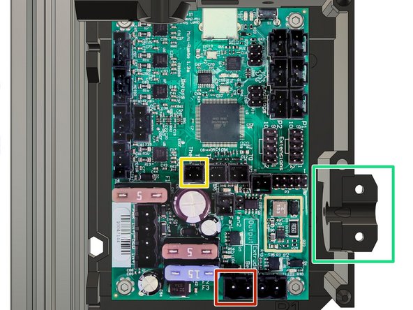
Insert the heated bed wiring and textile sleeve (or spiral wrap) through the right of the electronics cover. Secure them with the printed part and 2x M3x10 screws and 2x M3 square nuts.
-
This is image shows the design of the MK3 B7/R3 or MK3S electronics cover. The MK3 B3/R2 design is slightly different. Refer to the Prusa guide if necessary.
-
Using a Philips screwdriver, connect the heated bed wires:
-
Positive, red wire, connects to the screw terminal indicated by the red circle in the image
-
Negative, black wire, connects to the screw terminal indicated by the black circle in the image.
-
Tighten the screws firmly.
-
Double check that you have connected the wires in the correct order and orientation. Note that the wire terminal should go under the washer of the screw terminal.
-
-
-
Direct links to the original Prusa electronics assembly guides: MK3 (B3/R2 design), MK3 (B7/R3 design), MK3S.
-
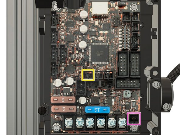
Plug in the following connectors:
-
Heated bed thermistor (has green heat shrink).
-
Power Panic (black and white wires).
-
You can now adjust the placement of the cables running along the back of the frame, if necessary, and carefully tighten the zip ties.
-
With a zip tie, bundle all of the cables, including the LCD cables and the Z motor on the X motor side, together.
-
Make sure there is no tension on the wires and none are pinched. Do not over-tighten the zip ties as you might damage the wires.
-
Check that all connectors are properly plugged in and tight.
-
-
-
Direct links to the original Prusa electronics assembly guides: MK3 (B3/R2 design), MK3 (B7/R3 design), MK3S.
-
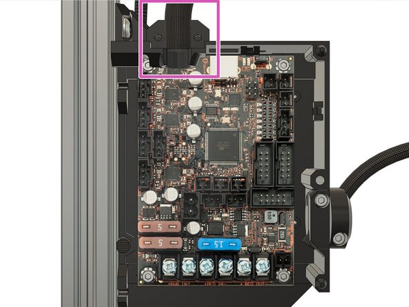
Before installing the extruder cables, twist the textile sleeve (not the cables) a turn or two.
-
This is useful to prevent cables going out of the textile sleeve when extruder move during a print.
-
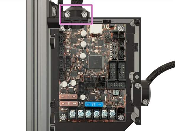
Insert the extruder wiring and textile sleeve (or spiral wrap) through the top of the electronics cover. Secure them with the printed part and 2x M3x10 screws and 2x M3 square nuts.
-
This is image shows the design of the MK3 B7/R3 or MK3S electronics cover. The MK3 B3/R2 design is slightly different. Refer to the Prusa guide if necessary.
-
Verify that the plug-aligner is still in place and correctly oriented.
-
-
-
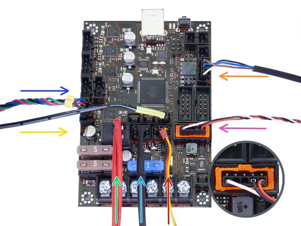
Plug in all of the cables from the extruder:
-
Extruder heater
-
Hotend fan
-
Print fan (has a red heat shrink)
-
Filament sensor. Both the IR (magnets and ball, MK2.5S/MK3S) and laser (MK2.5/MK3) sensors have to be connected to the lower row and have the red wire oriented toward the back of the frame.
-
Extruder motor
-
Extruder thermistor (has yellow and green heat shrink).
-
PINDA probe
-
-
-
Direct links to the original Prusa electronics assembly guides: MK2(S), MK2.5, MK2.5S
-
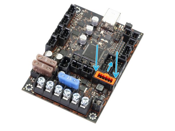
Plug in the LCD connectors:
-
LCD cable with TWO stripes (named EXP2 on the LCD board)
-
LCD cable with ONE stripe (named EXP1 on the LCD board)
-
Check that all connectors are properly plugged in and no wire is under tension or pinched!
-
-
-
The following steps are applicable to all of these versions of Prusa printers through to the end of this chapter.
-
-
-
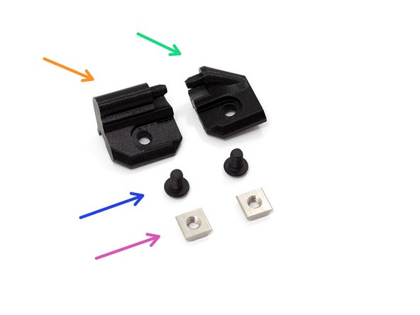
Prepare the following parts:
-
rambo_hinge_upper (might be slightly different depending on the Prusa model you are building)
-
rambo_hinge_lower (might be slightly different depending on the Prusa model you are building)
-
2x M5x8 screws
-
2x t-nuts
-
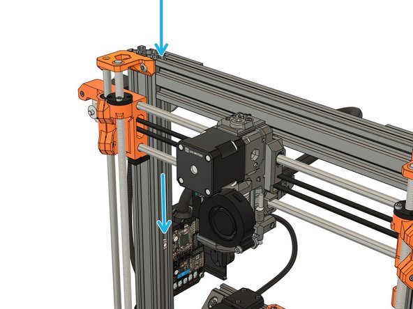
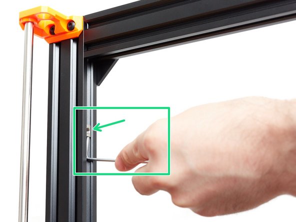
Insert 1x t-nut, into the extrusion, from the top, as shown. It will fall down to the joining plate but we are going to show you a little trick in the next step.
-
-
-
If you can't achieve this trick, simply rotate the frame to its left side. Be careful with the extruder as it will slide down.
-
Using a hex key (or a zip tie) move the t-nut upper and hold it in place with one hand.
-
Use a hex key 0f 2.5mm size or lower.
-
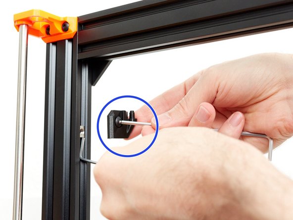
Take the rambo_hinge_lower and add an M5x8 screw in the biggest hole. Hold the part and a 3mm hex key with your other hand as shown in the image.
-
Place the rambo_hinge_lower on the t-nut and tighten the M5x8 screw. Do not tighten completely yet, we will need to slide it down.
-
You can remove the smaller hex key once the screw is engaged on the t-nut.
-
Tech tip: Keep in mind the technique we are using here for later when you will add accessories or do some maintenance on the printer.
-
-
-
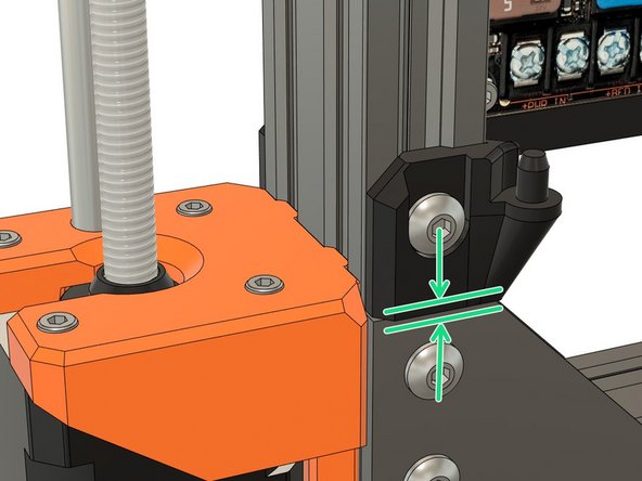
Slide the rambo_hinge_lower down to the joining plate and tighten the M5 screw fully.
-
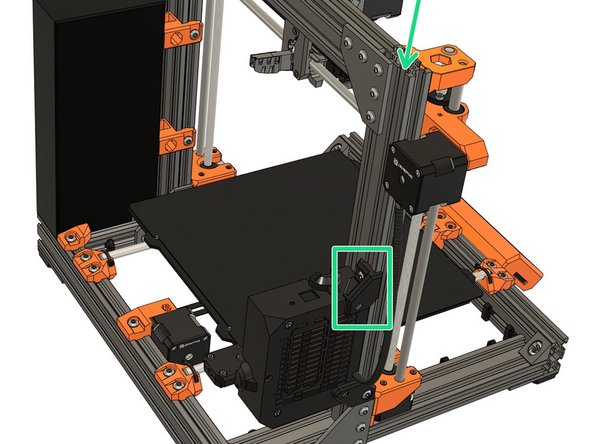
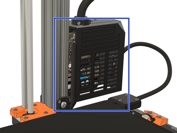
Place the electronics cover door on the rambo_hinge_lower.
-
Install the rambo_hinge_upper with an M5x8 and a t-nut using the same technique as in the previous step. Tighten the screw fully.
-
Make sure you can still open and close the door.
-
-
-
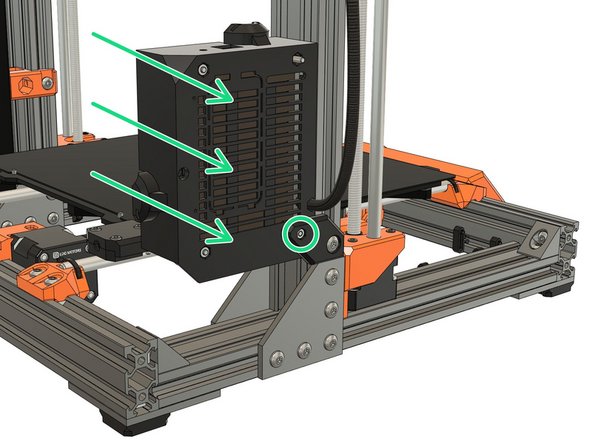
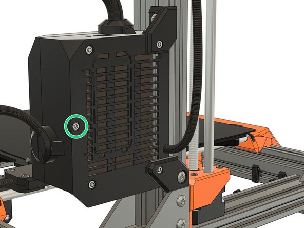
Secure the electronics cover door with an M3x40 screw (reused from your original Prusa).
-
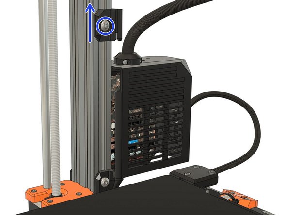
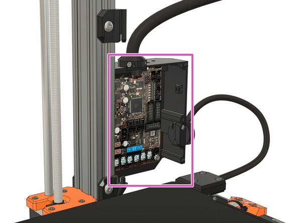
Tech tip: when you need to access the electronics, it is helpful to remove the door completely. On the Bear frame it is very easy:
-
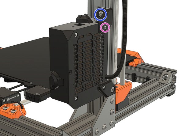
Partially unscrew the rambo_hinge_upper, move it higher up and tighten it in place.
-
Unscrew the M3x40 screw (green circle of 1st image). You can now remove the door completely and have better access to the electronics.
-
-
-
Congratulations you have finished this chapter :)
-
Go to the last chapter: 10. Final adjustments
-


Cancel: I did not complete this guide.
26 other people completed this guide.
