
-
-
Ensure the hotend has cooled down and turn off the printer.
-
Place a sheet of paper on your heated bed. Remove any residual filament coming out of the nozzle.
-
Center your extruder on the X axis. Move it down by rotating both the Z lead screws at the same time. Move the extruder down until the nozzle is just touching the paper.
-
Stop when the nozzle is just touching the paper.
-
Place the middle section of a zip tie under the Pinda.
-
Loosen the M3x10 screw and gently move the PINDA down until it is touching the zip tie.
-
Tighten the M3x10 screw to secure the PINDA in place.
-
-
-
Plugin and turn on the printer.
-
Using the screen menu, move the X axis up until it crashes in to the Z tops. The stepper motors will skip. making a noise - this will not damage the motors.
-
Using the screen menu, move the X axis down until the nozzle is approximately 10-15mm from the heated bed.
-
-
-
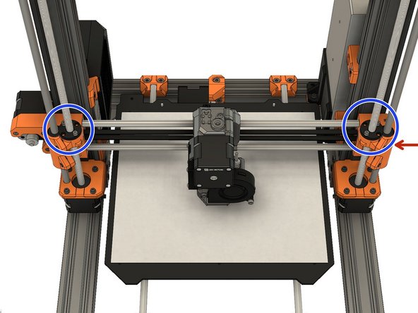
If you have applied tension to the belt, unscrew the belt tensioner on x_end_idler until the belt is relaxed.
-
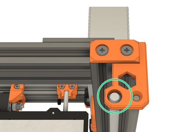
Loosen the screws which secure the trapezoidal nuts. This is to ensure that the Trapezoidal nuts 'self-centre' on the lead screws.
-
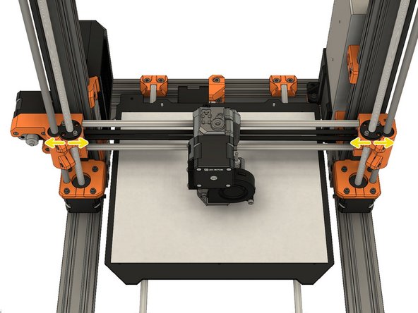
Make sure the trapezoidal nuts are moving freely.
-
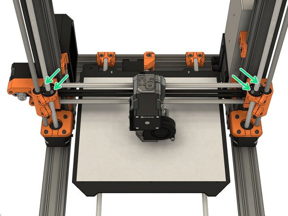
Tighten the 4 screws alternately (on both sides). Don't apply any lateral force on the trapezoidal nuts.
-
-
-
Move the X axis to the middle of the Z axis and shutdown the printer.
-
Tighten the belt until the belt is straight and doesn't sag. Don't tighten too much, you should still be able to pinch the belt with very little force force.
-
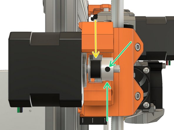
Loosen the two pulley set screws a little.
-
Adjust position of the pulley to have the belt centred. You can move the extruder by hand, to the left and right, to verify that the belt is centred.
-
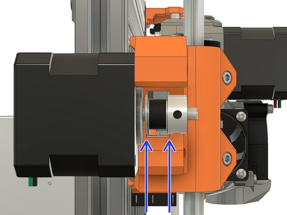
Tighten the set screws alternately.
-
Verify that the belt is not touching the x_end_motor and that the drive pulley is not touching the X motor.
-
-
-
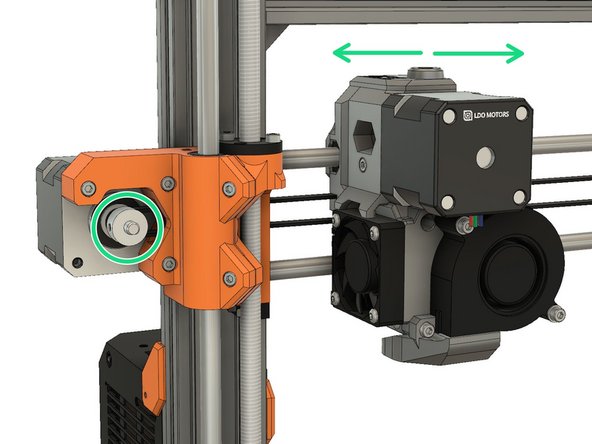
Grip the X motor shaft with pliers to prevent it moving (grab the flat side of the shaft). Tension the belt, by tightening the screws in the x_end_idler. Do this while trying to move the extruder to the left or right. The belt should stay straight and should not bow up and skip over the drive pulley teeth.
-
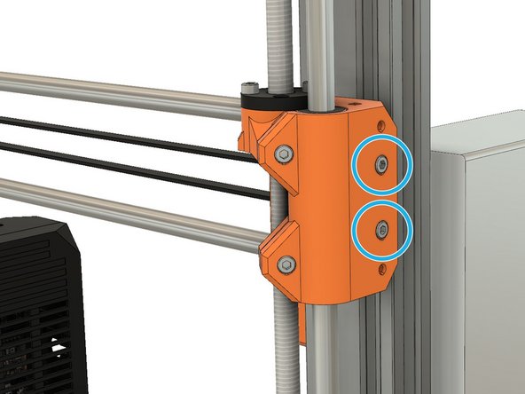
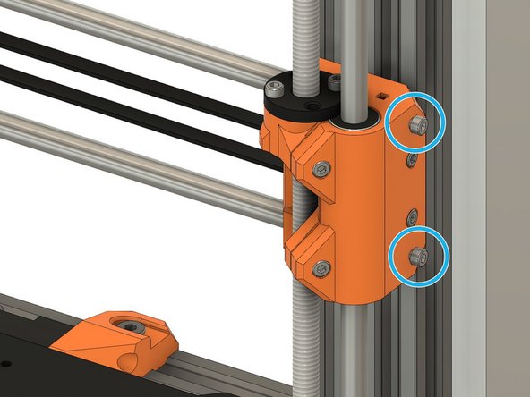
Thread two M3x10 screws in the x_end_idler. Don't tighten them fully yet, it will be done on the next step.
-
-
-
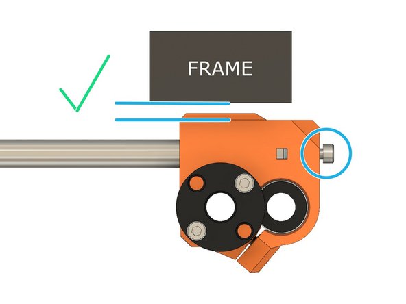
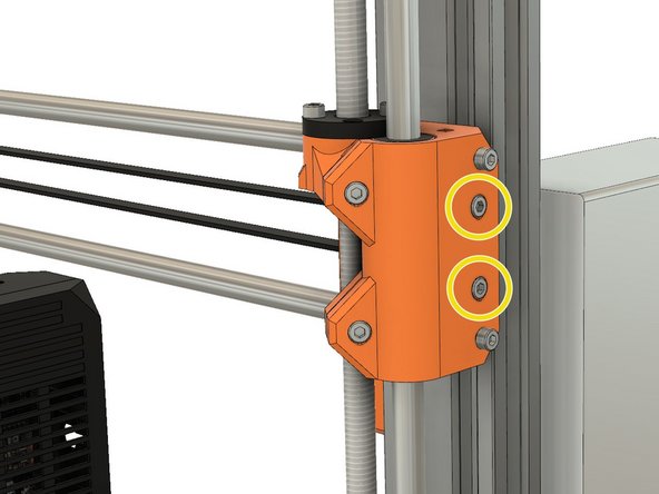
Adjust both M3x10 screws to have the x_end_idler parallel to the frame.
-
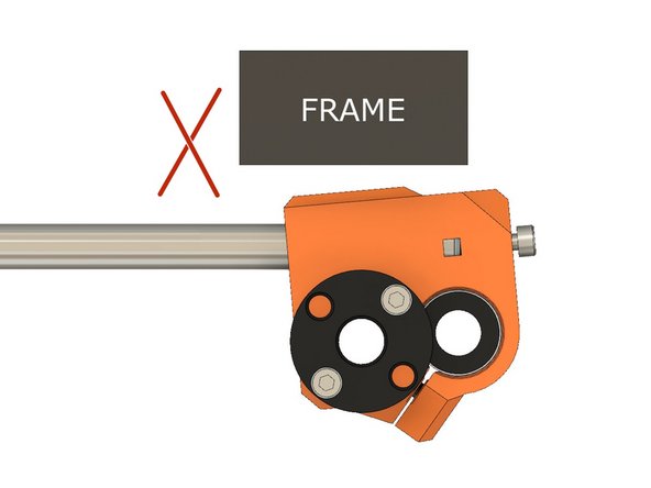
Second image shows when the X axis is too short. In this case you need to tighten the two M3x10 screws.
-
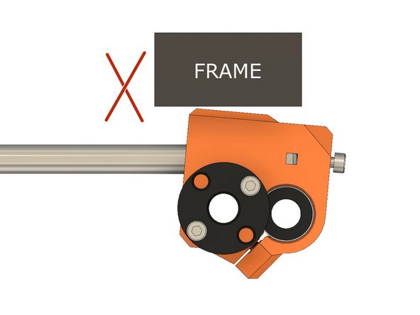
Third image shows when X axis is too long. In this case you need to unscrew the two M3x10 screws.
-
It might happen that with excess tension on the M3x10 screws, the Z smooth rods will start to be off center on the Z tops. In this case release tension even if the x_end_idler is not totally parallel to the frame.
-
Check the next step if you have difficulty to see if the x_end_idler is parallel to the frame.
-
-
-
If you have difficulty to see if the x_end_idler is parallel to the frame you can use a thick ruler or a square like on the first image.
-
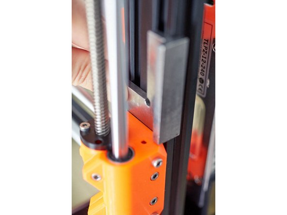
Verify that your Z lead screw is not touching the Z tops holes. If it is touching release the pressure from the X smooth rods tensioning screws like explained in the previous step.
-
Note that Z lead screw does not need to be centered totally, it ca wobble a little.
-
Double check that your belt is still well tensioned. In case it needs adjustment repeat the previous step.
-
-
-
For improved reliability and print quality, the Bear extruder is slightly taller than the original MK2.5S/MK3S extruder. We provide customized firmware to pass Selftest and (XY)Z Calibration. After those steps you have the choice to keep using our customized firmware or flash stock firmware. In either case, you use our firmware at your own risk.
-
Select and download the latest Bear calibration firmware here: github.com/bear-lab-3d/Prusa-Firmware/re...:
-
MK3S Einsy-Rambo 10a firmware name: Bear_Cal_FW***_MK3S-EINSy10a.hex
-
MK2.5S Mini-Rambo 13a firmware name: Bear_Cal_FW***_MK25S-RAMBo13a.zip
-
MK2.5S Mini-Rambo 10a firmware name: Bear_Cal_FW***_MK25S-RAMBo10a.zip
-
MK2.5S firmware comes as a ZIP file containing several languages of the firmware. They all contains english. Extract the ZIP file and choose the language you prefer to use (in addition of english).
-
If you don't know which Mini-Rambo board you have, please refer to this document
-
-
-
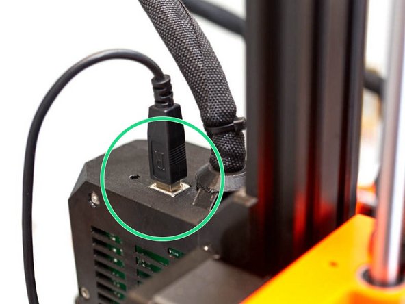
Get a USB A to B cable.
-
Connect the USB cable on the Mini-Rambo / Einsy-Rambo.
-
Connect the other side of the USB cable to your computer that is running PrusaSlicer.
-
We recommend that you use PrusaSlicer to flash firmware.
-
Turn on the printer.
-
-
-
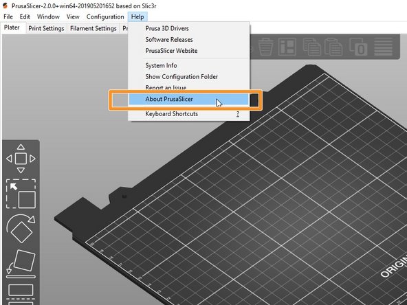
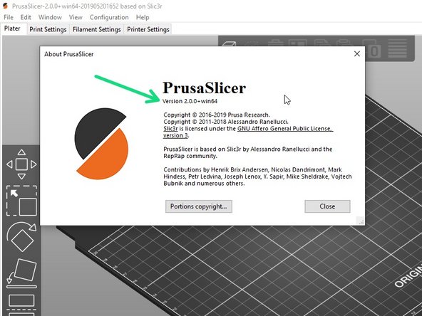
Start PrusaSlicer software and go to the top menu Help -> About ...
-
Verify that the slicer version is equal or greater than 2.0.0.
-
If version is equal or greater: go to the next step
-
If your version is lower: download and install the version shown above from this page: prusa3d.com/prusaslicer.
-
You can update to the most recent version, however, we may not have tested with that version.
-
-
-
Verify that the printer is turned on.
-
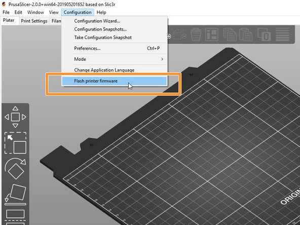
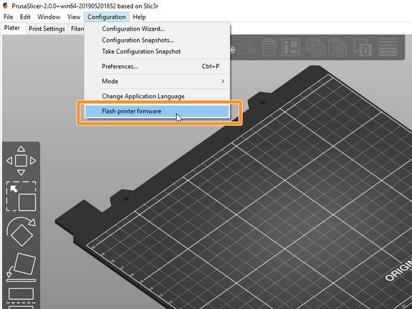
Start PrusaSlicer and navigate to the top menu Configuration -> Flash print firmware
-
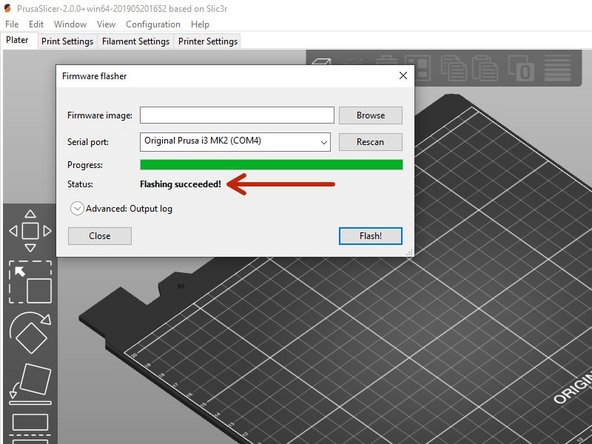
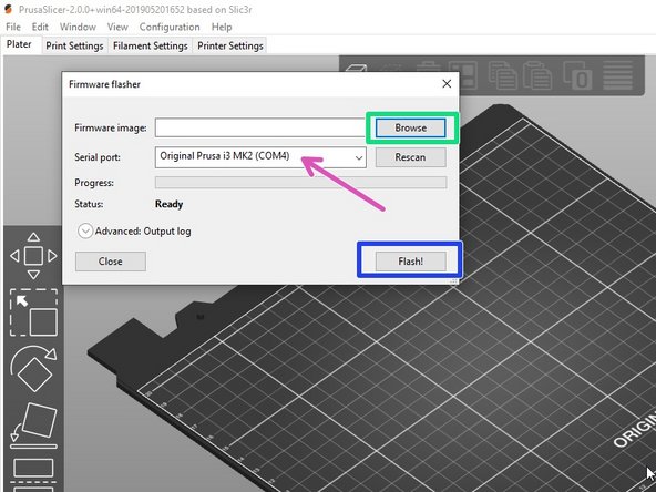
Select the appropriate Bear calibration firmware *.hex file using the Browse button.
-
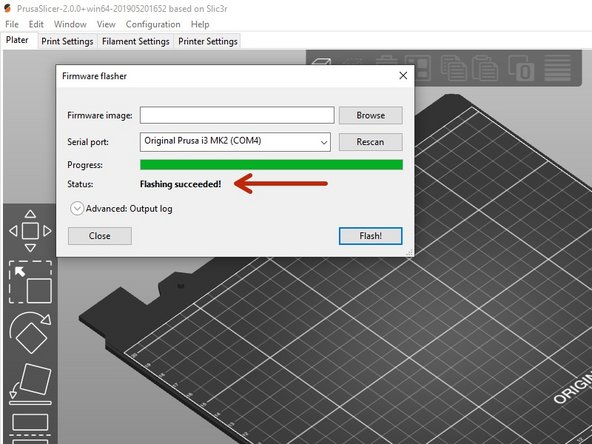
Verify that the printer is detected in the "Serial port:" window. If not, check that the USB cable is firmly connected to both the printer and the computer. select "Rescan"
-
Click the button Flash! to flash the Bear calibration firmware.
-
Never turn off the printer or disconnect the USB cable while flashing the firmware!
-
Wait until you get a Flashing succeeded! message.
-
In case of issues while flashing the firmware read the Prusa troubleshooting article.
-
-
-
Turn the printer off and and then on.
-
Run the "Selftest" in calibration settings.
-
If errors occur during selftest, please fix them before going further.
-
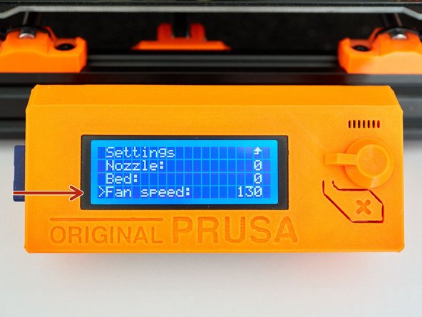
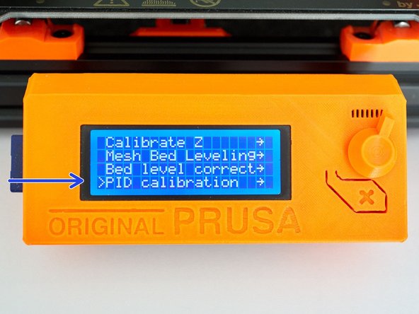
In Settings -> Temperature -> Fan speed set a value at 130 if you print lots of PETG and 255 if you print lots of PLA. For other materials select according to your most used filament.
-
Run PID calibration in calibration settings.
-
Choose a temperature that matches your most used printing temperature.
-
-
-
Heat up the nozzle by selecting Settings -> Temperature -> Nozzle: and insert PLA filament.
-
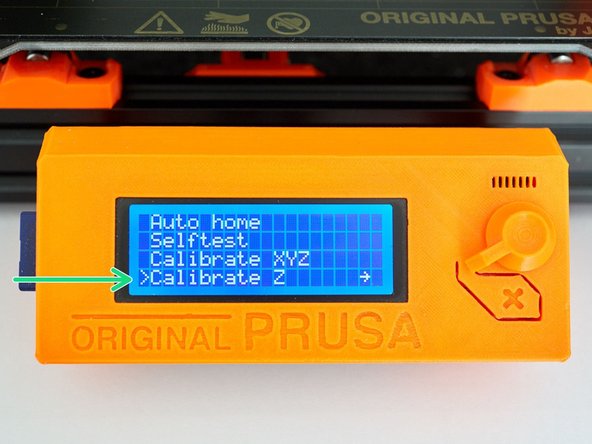
Make sure you have the steel sheet on the printer.
-
Run Calibration Z. You may repeat the procedure.
-
Because the extrusion multiplier and filament diameter are not calibrated yet, it will only give a first approximation of the first layer height.
-
-
-
We recommend to now flash back the stock Prusa firmware. The custom firmware is only needed for (XY)Z Calibration and Selftest, all other features of the original firmware are working normally. If you like you can continue to use our custom firmware at your own risk.
-
Select and download the latest Prusa firmware here: prusa3d.com/drivers :
-
MK3S Einsy-Rambo 10a firmware name: FW_MK3S-EINSy10a.hex
-
MK2.5S Mini-Rambo 13a firmware name: FW_MK25S-RAMBo13a.zip
-
MK2.5SMini-Rambo 10a firmware name: FW_MK25S-RAMBo10a.zip
-
MK2.5S firmware comes as a ZIP files containing several languages of the firmware. Extract the ZIP file and choose the language you prefer the most.
-
If you don't know which Mini-Rambo board you have, please refer to this document
-
-
-
Verify that the printer is turned on and USB connected.
-
Start PrusaSlicer and navigate to the top menu Configuration -> Flash print firmware
-
Select the Bear calibration firmware *.hex file using the Browse button.
-
Verify that the printer is detected in the "Serial port:" window. If not, check that the USB cable is firmly connected to both the printer and the computer. select "Rescan"
-
Click the button Flash! to flash the Bear calibration firmware.
-
Never turn off the printer or disconnect the USB cable while flashing the firmware!
-
Wait until you get a Flashing succeeded! message.
-
In case of issues while flashing the firmware read the Prusa troubleshooting article.
-
-
-
Follow our "Extrusion multiplier" guide here: 8. Extrusion multiplier and filament diameter
-
-
-
Congratulations, you have finished to install and calibrate your Bear extruder.
-
Happy printing :)
-


Cancel: I did not complete this guide.
9 other people completed this guide.
