-
-
Ensure the hotend has cooled down and turn off the printer.
-
Remove the steel sheet and place a sheet of paper on your heated bed. Remove any residual filament from the nozzle.
-
Center your extruder on the X axis. Move it down by rotating both the Z lead screws at the same time. Move the extruder down until the nozzle is just touching the paper.
-
Make sure the X axis is flat. You can move the extruder left and right and compare the distance with the heated bed.
-
Stop when the nozzle is just touching the paper.
-
Place the middle section of a zip tie under the Pinda.
-
Loosen the M3x10 screw and gently move the PINDA down until it is touching the zip tie.
-
Tighten the M3x10 screw to secure the PINDA in place.
-
-
-
Plugin and turn on the printer.
-
Using the screen menu, move the X axis up until it crashes in to the Z tops. The stepper motors will skip, making a noise - this will not damage the motors.
-
If your printer can't reach the Z tops, unplug the printer and plug it back. You can now reach Z tops.
-
Using the screen menu, move the X axis down until the nozzle is approximately 10-15mm from the heated bed.
-
-
-
Turn off the printer and center the extruder.
-
If you have applied tension to the belt, unscrew the belt tensioner on x_end_idler until the belt is relaxed.
-
Loosen the screws which secure the trapezoidal nuts. This is to ensure that the Trapezoidal nuts 'self-centre' on the lead screws.
-
Make sure the trapezoidal nuts are moving freely.
-
Alternate between all 4 screws evenly while tightening (alternate between both sides during the process). Don't apply any lateral force on the trapezoidal nuts.
-
-
-
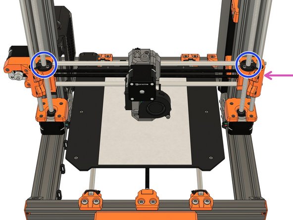
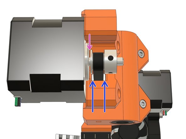
Loosen both pulley set screws a little.
-
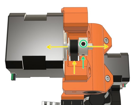
Align the pulley with the belt hole of the x_end_motor.
-
Tighten the set screws alternately.
-
Verify that the belt is not touching the x_end_motor.
-
Verify that the drive pulley is not touching the X motor.
-
-
-
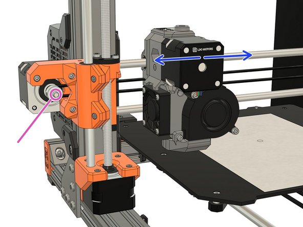
Grip the X motor shaft with pliers to prevent it moving (grab the flat side of the shaft).
-
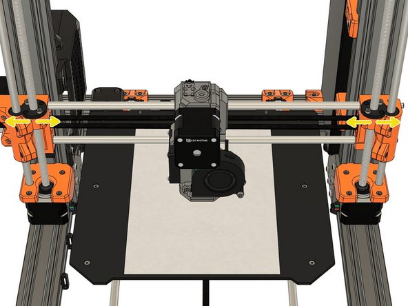
Tension the belt, by tightening the screws in the x_end_idler. Do this while trying to move the extruder to the left or right. The belt should stay straight and should not bow up and skip over the drive pulley teeth.
-
No need to be very precise with the belt tension here as the final tension will be improved later.
-
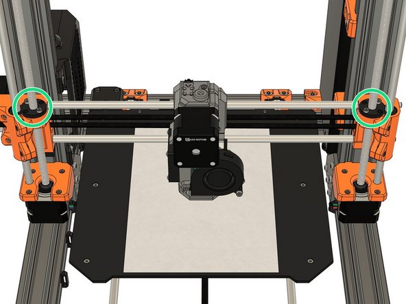
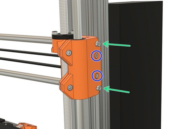
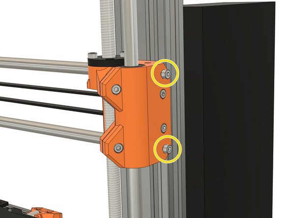
Thread two M3x10 screws inside the top and bottom holes of x_end_idler. Do not screw them fully, leave a gap of 1-2mm as shown on the third image.
-
-
-
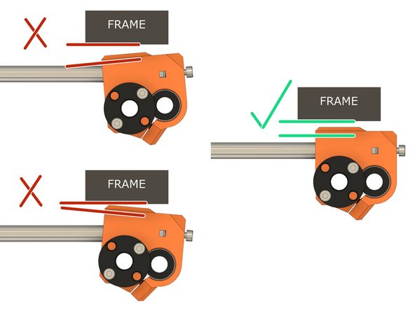
Not all X axis have the exact same length because of tolerances (including on Original Prusa printers). This step will adjust your X axis length.
-
The 1st image shows what happens to the X ends when you tension the X axis belt. We want to have the X ends as parallel as possible to the frame (or it will affect the X belt motion).
-
1st image, top left: when the X axis is too short.
-
1st image, bottom left: when X axis is too long.
-
1st image, right: when the X axis has the perfect length.
-
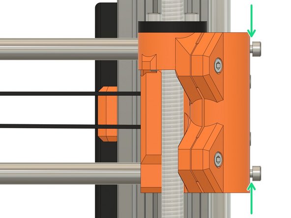
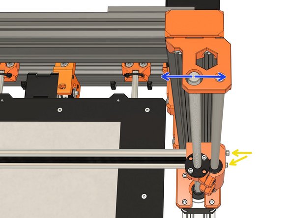
To adjust the length of the X axis we need to use the two M3x10 screws of the x_en_idler and look at the Z tops.
-
While you tighten the M3x10 screws keep an eye on the Z tops. The M3x10 screws will move the Z leadscrews laterally (left or right), adjust them to have the Z leadscrews as possible centered.
-
Note that the M3x10 screws will not move back and forth the Z lead screw position, only laterally.
-
-
-
To set perfect belt tension we will make it vibrate and tune it to a certain frequency, just like a guitar. To do that we will use a smartphone application.
-
Download and install the Pano Tuner application (developed by Kaleloft LLC) on your smartphone.
-
-
-
Turn off the printer (if your hotend is higher than 50°C, let the hotend cool down first until the hotend fan stops spinning)
-
Launch the Pano Tuner app and place your smartphone on the heated bed. Make sure there is no noise in the room that could disrupt the measurement (like a ceiling fan).
-
-
-
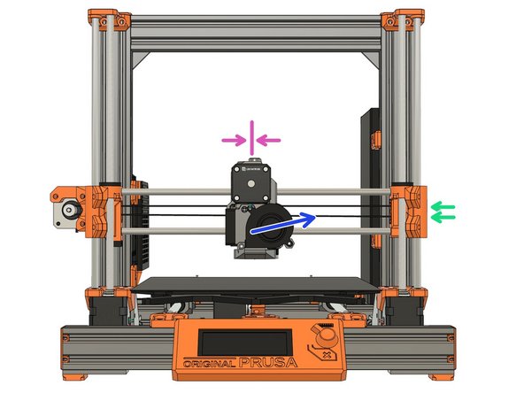
Move the extruder to the middle of the X axis.
-
Pluck the lower belt to make it vibrate. Don't pluck it too much as it might touch the carriage and produce a wrong frequency.
-
Adjust the belt tension until you have a value around 90Hz. Between each adjustment, move the extruder to all the way to the left and right and then center it again.
-
It is very important to move left and right the extruder between each measurement to relax some tension in the belt.
-
If your belt is new, you can repeat this procedure after a few prints. A new belt will loosen in the first hours of use.
-
-
-
For improved reliability and print quality, the Bear extruder is slightly taller than the original MK2.5S/MK3S extruder. We provide customized firmware to pass Selftest and (XY)Z Calibration for the taller size of the Bear exturder. Our firmware also provides a faster and safer rotation for hotend fan (if using something different than Noctua).
-
After the self test, you can go back to Prusa firmware if you prefer. However, you will have to use the stock hotend fan (Noctua).
-
Select and download the latest Bear calibration firmware here: github.com/bear-lab-3d/Prusa-Firmware/re...:
-
MK3S Einsy-Rambo 10a firmware name: Bear_Cal_FW***_MK3S-EINSy10a.hex
-
MK2.5S Mini-Rambo 13a firmware name: Bear_Cal_FW***_MK25S-RAMBo13a.zip
-
MK2.5S Mini-Rambo 10a firmware name: Bear_Cal_FW***_MK25S-RAMBo10a.zip
-
MK2.5S firmware comes as a ZIP file containing several languages of the firmware. They all contain English. Extract the ZIP file and choose the language you prefer to use (in addition to English).
-
If you don't know which Mini-Rambo board you have, please refer to this document
-
-
-
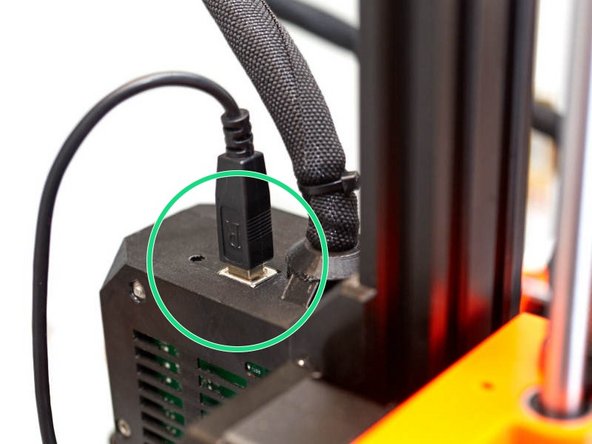
Get a USB A to B cable.
-
Connect the USB cable to the Mini-Rambo / Einsy-Rambo.
-
Connect the other side of the USB cable to a computer that is running PrusaSlicer.
-
We recommend to you use PrusaSlicer to flash the firmware.
-
Turn on the printer.
-
-
-
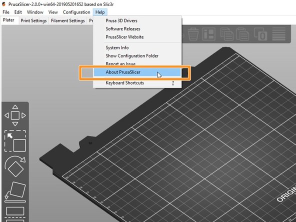
Start PrusaSlicer and go to the top menu Help -> About ...
-
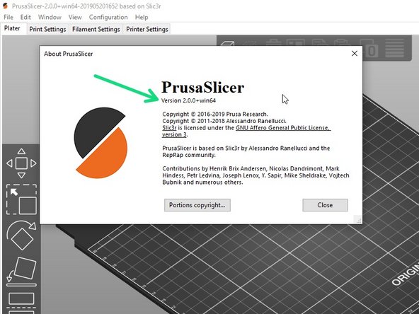
Verify that the slicer version is equal or greater than 2.0.0.
-
If the version is equal or greater: go to the next step
-
If your version is lower: download and install the version shown above from this page: prusa3d.com/prusaslicer.
-
You can update to the most recent version, however, we may not have tested with that version.
-
-
-
Verify that the printer is turned on.
-
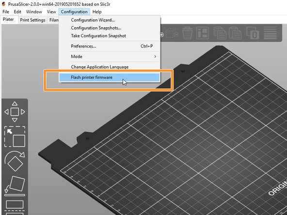
Start PrusaSlicer and navigate to the top menu Configuration -> Flash printer firmware
-
Select the appropriate Bear calibration firmware *.hex file using the Browse button.
-
Verify that the printer is detected in the "Serial port:" window. If not, check that the USB cable is firmly connected to both the printer and the computer. select "Rescan"
-
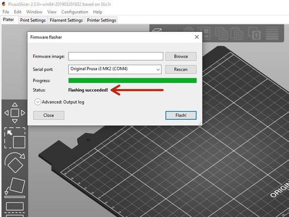
Click the button Flash! to flash the Bear calibration firmware.
-
Never turn off the printer or disconnect the USB cable while flashing the firmware!
-
Wait until you get a Flashing succeeded! message.
-
In case of issues while flashing the firmware read the Prusa troubleshooting article.
-
-
-
Turn the printer off and and then on.
-
Run the "Selftest" in calibration settings.
-
If errors occur during selftest, please fix them before going further.
-
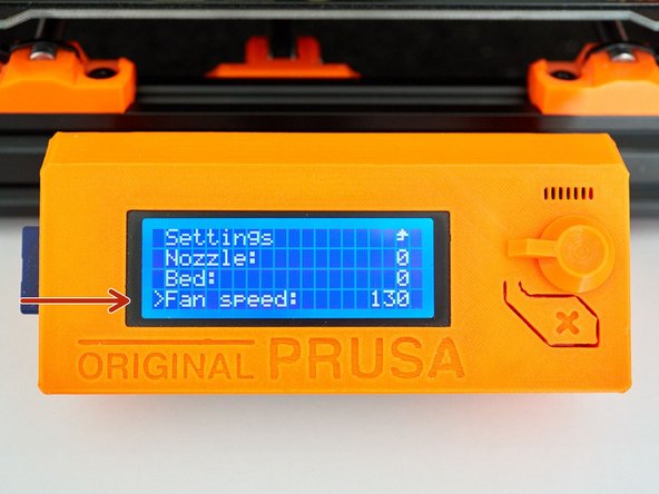
In Settings -> Temperature -> Fan speed set the value at 130 if you print lots of PETG and 255 if you print lots of PLA. For other materials select a value suitable for your most used filament.
-
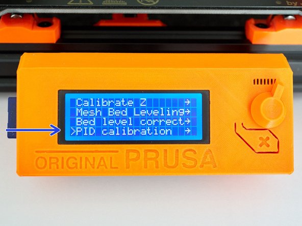
Run PID calibration in calibration settings.
-
Choose a temperature that matches your most used printing temperature.
-
-
-
Heat up the nozzle by selecting Settings -> Temperature -> Nozzle: and insert PLA filament.
-
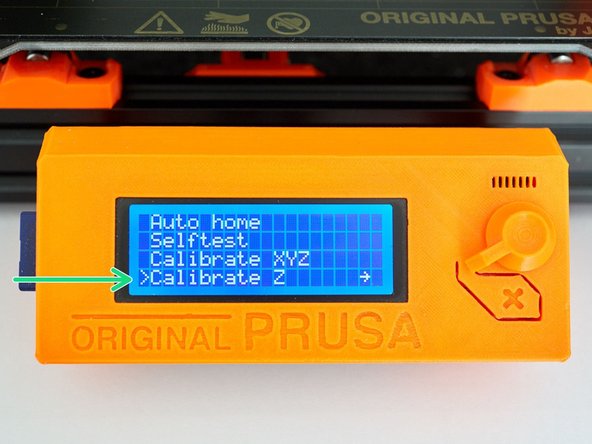
Make sure you have the steel sheet on the printer.
-
Run the Z Calibration.
-
Because the extrusion multiplier and filament diameter are not calibrated yet, it will only give a first approximation of the first layer height.
-
-
-
Follow our "Extrusion multiplier" guide here: 8. Extrusion multiplier and filament diameter
-
-
-
Congratulations, you have finished to install and calibrate your Bear extruder.
-
Happy printing :)
-