
-
-
The Bear frame is compatible with the Prusa stock extruder and X axis as well as the Bear extruders (BearExxa, BearMera and Bear X axis with Bondtech extruder).
-
If you are upgrading an existing Original Prusa save all the screws and nuts as some will be reused.
-
To save time later, check all of the printed parts. Check that screw holes are clear, to allow the screws to slide in without excessive force.
-
Some steps are showing the Original MK3(S) frame but they are applicable to MK2(S)/MK2.5(S) frame as well.
-
Disclaimer: We share these guides to make your experience as smooth as possible. However, you are responsible for your upgrade, assembly and any damage you cause to your hardware. Therefore we cannot be taken as responsible in case of damage due to the steps presented in our guides.
-
-
-
Check that your kit contains 7 aluminium extrusions of the following 4 lengths.
-
290mm
-
331mm
-
359mm
-
370mm
-
If you have the MK2(S) or MK2.5(S) Bear 2.0 older shorter frame then the lengths will be different:
-
311mm
-
356mm
-
-
-
Clean up strings from your printed parts with tweezers and a hot air gun (be careful).
-
Carefully check the inside of the holes in the X ends, where the smooth rods will be inserted.
-
Remove any elephants foot with a deburring tool or a file.
-
Check all bridges. If a bridge is falling in its center: heat tweezers with a lighter and press on the area with the poor bridging, to flatten it.
-
-
-
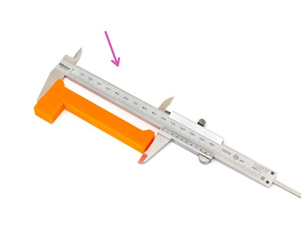
With a caliper, verify the length of the build_helper_z. It must be:
-
106mm +/- 0.5mm for the MK3(S)(+) or MK2.5(S)(+)
-
96mm +/- 0.5mm if you have the MK2(S) or MK2.5(S) Bear 2.0 older shorter frame
-
In case it is too long you can file one of the end.
-
In case it is too short you can scale it using PrusaSlicer and reprint.
-
Only use one build helper. This is to ensure that both z extrusions are set to the same distance.
-
-
-
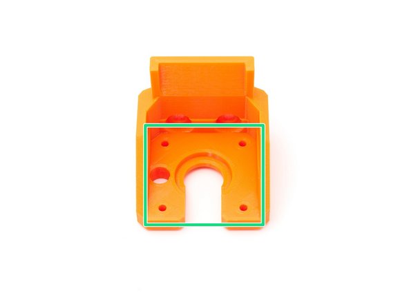
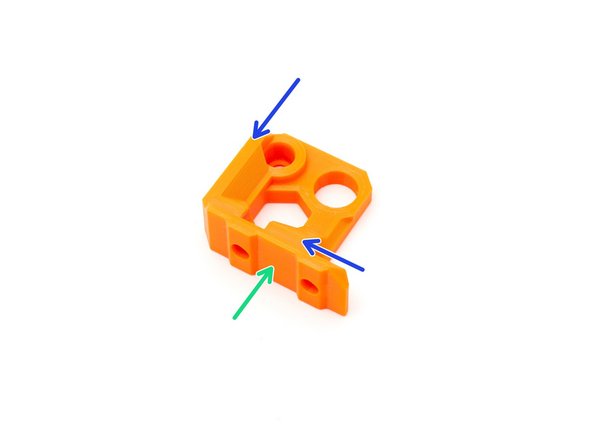
Verify that the internal surfaces of the z_motor_mount are smooth and flat. Clean up if necessary using a file or small scraper (you can use a steel rule if you don't have a small scraper).
-
Verify that the surfaces that will be in contact with the extrusions are smooth and flat.
-
Take one of the Z smooth rods, which you disassembled from your Prusa, and test fit it into the Z motor mount hole.
-
If it is too hard to insert the smooth rods you can use an 8mm drill or reamer to increase the hole diameter. Don't pass the drill / reamer through the full depth of the hole, only half of it is generally enough and will ensure you keep a tight fit. Remember, don't use a power tool, use your hands :) !
-
-
-
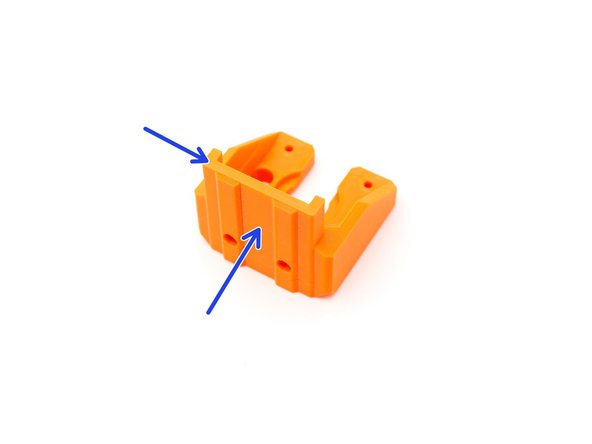
Verify that the surfaces on the back of the z_tops are smooth and flat.
-
Verify that the surfaces that will be in contact with the X axis (X ends) are smooth and flat.
-
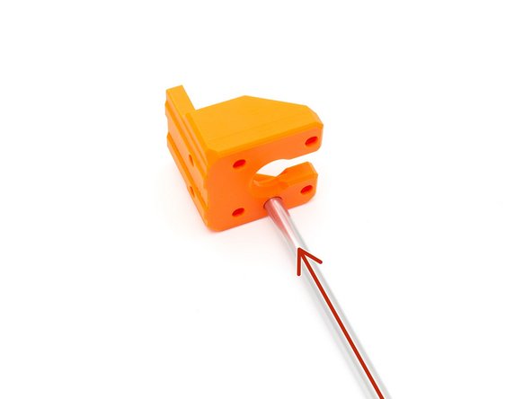
As in the previous step, test the 8mm hole by fully inserting a Z smooth rod.
-
If it is too hard to insert the smooth rods you can use an 8mm drill or reamer to increase the hole diameter. Don't pass through the full depth of the hole, only half of it is generally enough and will ensure you keep a tight fit. Remember, don't use a power tool, use your hands :) !
-
-
-
If you install a new BearExxa, BearMera or Bondtech with Bear X axis at the same time as the frame, you MUST do this verification before disassembling.
-
If you don't do it you might be unable to finish the assembly of your extruder.
-
If you are re-using an Original Prusa extruder you can skip this step.
-
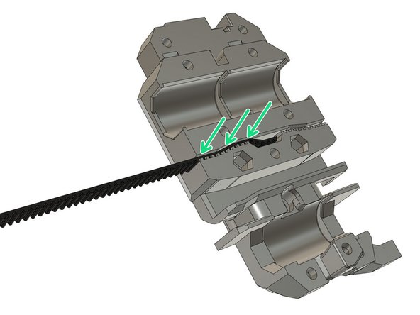
Try to insert the belt from your original Prusa in the Bear x_carriage. Use a slotted screwdriver to make sure the belt goes fully inside. If you have trouble inserting the belt, it might be due to the following issues:
-
Your prints are over-extruded. When you print functional parts you MUST calibrate your extrusion multiplier. This is not optional, every spool is different and will melt differently. Check our calibration guide: Extrusion multiplier and filament diameter .
-
You are not using a genuine Gates 2GT belt or your belt profile is not corresponding to 2GT.
-
You are using a different filament than plain PETG and the shrinkage coefficient is different. In this case, you can compensate for shrinkage within your slicer.
-
-
-
Unload the filament and allow the hotend to cool down (otherwise you might jam your hotend). Turn off the printer and remove the power plug.
-
Remove the spool and its holder.
-
During disassembly, it may be useful if you mark each smooth rod to identify it for later. A piece of tape indicating the x, y or z axis, for example.
-
If you have a doubt about what the part names are on your 3D printer, take a look at Prusa's glossary for the i3-series: https://help.prusa3d.com/en/article/glos...
-
Double check the printer is not connected to the outlet anymore.
-
-
-
Remove the M3x40 screw securing the Rambo/Einsy cover and disconnect all the cables.
-
Cut all zip ties that are used to attach cables to the frame.
-
Be careful not to cut the cables whilst cutting the zip ties.
-
Disassemble the extruder and remove it from the X axis. If you don't know how to proceed, we recommend that you follow the assembly guides in reverse.
-
Links to Prusa's assembly guides: mk3s, mk2.5s, mk3, mk2.5, mk2s
-
Links to Bear's extruder assembly guides: Bear extruders guides.
-
Links to Bondtech assembly guides: Bondtech extruders guides
-
-
-
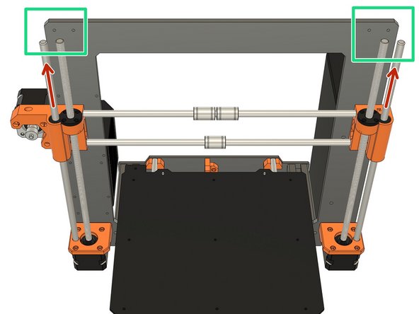
Remove the Z tops.
-
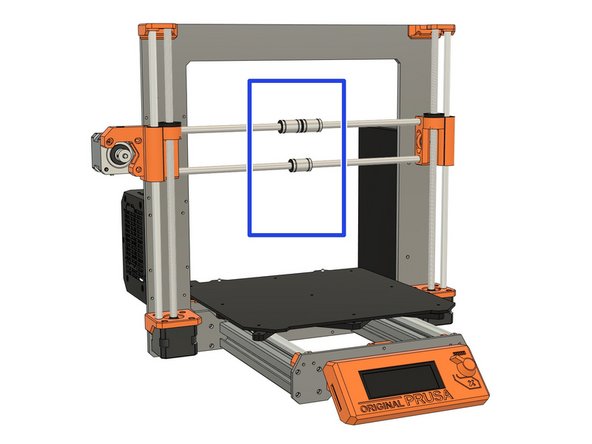
Remove the Z smooth rods.
-
Rotate the Z leadscrews, simultaneously, to move the X axis upwards so that you can remove the X axis. Take care to support the X axis, when you reach the top, and do not let if fall down.
-
Keep the X axis in one piece for re-assembly later.
-
-
-
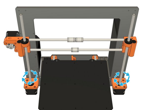
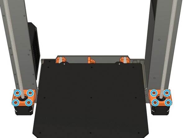
Unscrew the 8x Z motors screws. Be careful, the motors will fall down!
-
Unscrew the 6x Z motor mount screws. Lift the frame a little bit if you can't access them.
-
You can now slide out the motor mount from the leadscrews.
-
-
-
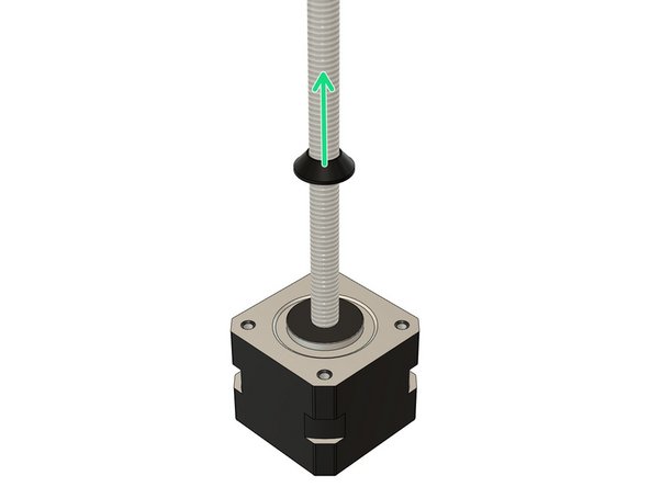
Unscrew the Z screw cover on both Z motors.
-
This step is mandatory as the original Z screw covers are not compatible with the Bear motor mounts.
-
-
-
Remove the Y axis belt.
-
Remove the Y motor. You do not need to remove the drive pulley.
-
Remove the Y idler mount and disassemble it, keeping the idler.
-
Remove the Y belt holder from the Y carriage.
-
-
-
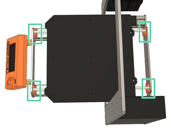
Remove the zip ties from the Y axis rod holders.
-
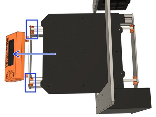
Un-clip the Y smooth rods from the front rod holders, slide the bed forward and remove it completely from the printer.
-
Remove both Y smooth rods from the frame.
-
-
-
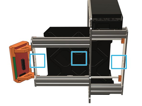
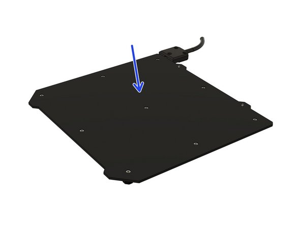
Dismount the heatbed from the Y carriage.
-
On MK3(S) there are 9 screws that needs to be unscrewed from the top (under the steel sheet).
-
On MK2(S), MK2.5(S) there are 5 screws that needs to be unscrewed from the bottom.
-
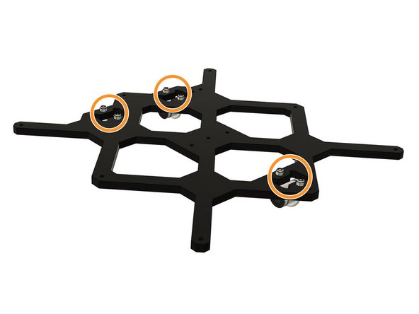
Undo the U bolts holding the bearings to the Y carriage.
-
-
-
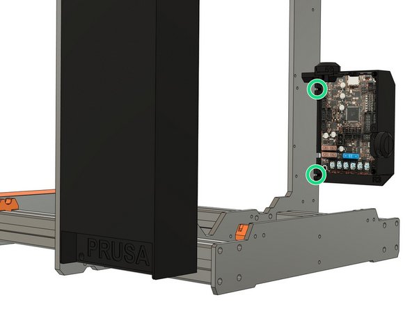
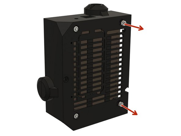
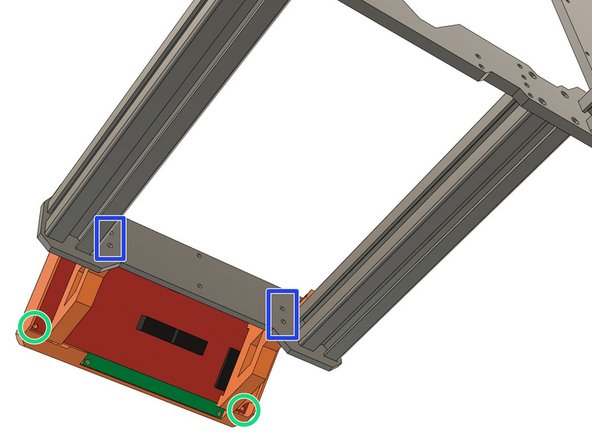
These images show the Rambo Einsy board and cover but the screws on other boards are in the same positions.
-
Remove the Rambo cover door and unscrew the M3 screws holding the cover.
-
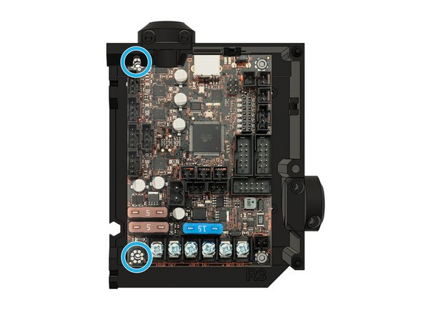
Remove the two M3 screws on the left of the Rambo board.
-
Do not unscrew the two screws on the right.
-
Remove the two hex nuts, on the right as viewed from the back of the Rambo cover. You can insert an M3 screw into them and pull.
-
-
-
Double check that the printer is not connected to an outlet.
-
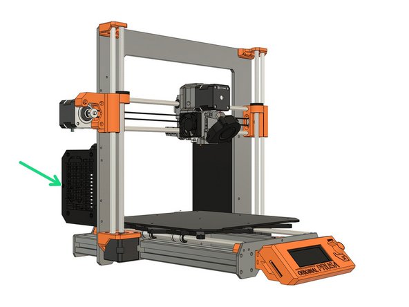
Remove the PSU from the frame.
-
There are different types of PSU, If you are unsure how to proceed with the disassembly, we recommend that you follow the assembly guides in reverse order.
-
Links to Prusa's assembly guides: mk3s, mk2.5s, mk3, mk2.5, mk2s
-
-
-
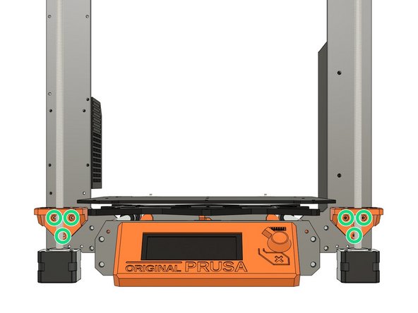
Dismount the LCD screen from the printer by removing the four M3 screws from the front plate.
-
Disassemble the LCD support by removing the two screws at the bottom of the LCD's board.
-
-
-
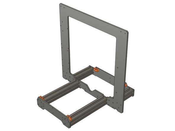
Say good bye to your old frame :) .
-
Please consider recycling the frame by building another printer or selling it on the second hand market.
-
Got to the next chapter: 03. Y axis frame
-


Cancel: I did not complete this guide.
33 other people completed this guide.
