Difficulty
Difficult
Steps
23
Time Required
- 03. Y axis frame 23 steps

In Progress
This guide is currently being written. Reload periodically to see the latest changes.

Private
This guide will not appear in search results and can only be viewed by team members!
Quiz
0
-
-
We are using t-nuts to attach parts and plates to the extrusions. These t-nuts slide inside the extrusion.
-
The Bear Upgrade 2.1 comes with custom designed t-nuts that can only be inserted in the correct orientation.
-
If you use Openbuilds hardware or other kits your t-nuts need to be inserted in a certain orientation.
-
Tech note: our new t-nuts reduce the chance of damaging the frame, have a longer and more precisely machined thread and being manufactured from stainless steel, they are rust free.
-
-
-
Here are some tips on how to tighten screws; to avoid damage, to make alignment easier and to ensure consistently torqued screws.
-
If you have several screws to tighten together, always tighten them incrementally until they are snug.
-
When you have 3 screws you can follow this tightening sequence:
-
Start with the middle one
-
Continue to the second one
-
Tighten the third one and repeat until all screws are snug.
-
-
-
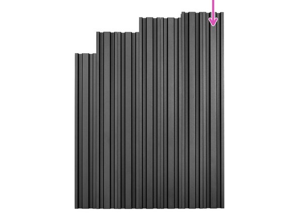
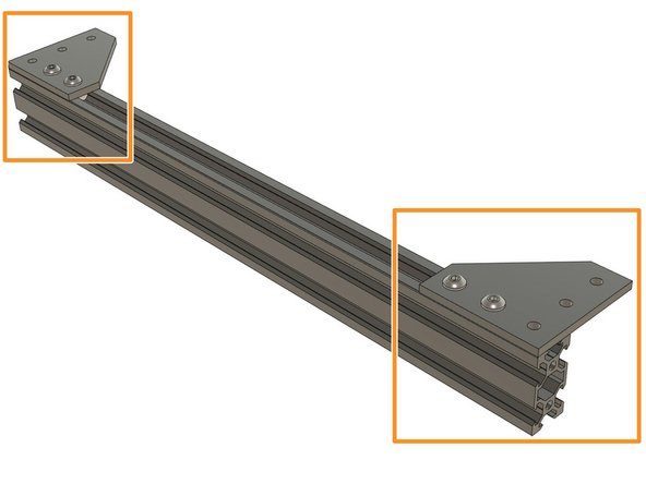
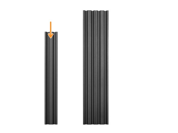
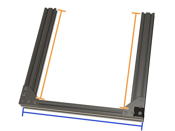
Take one of two longest extrusions. It is 370mm long.
-
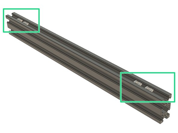
On the 20mm face of the extrusion, slide 2x t-nuts on each side (4x t-nuts in total).
-
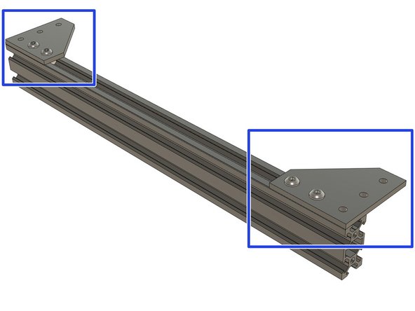
Bolt 2x joining plates on the t-nuts using 4x M5x10mm screws. Do not tighten them fully yet.
-
-
-
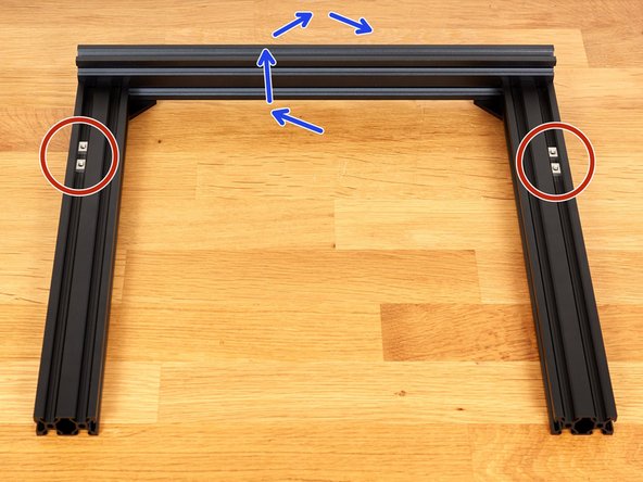
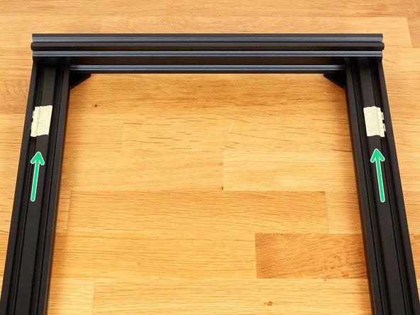
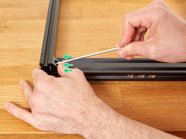
Take your time with this step.
-
Make sure that you are workng on a flat and level surface.
-
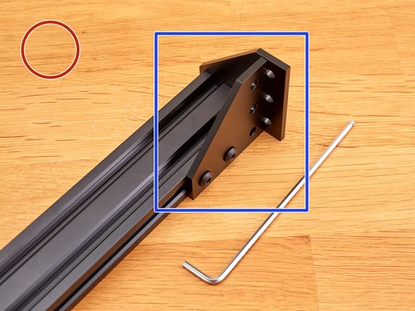
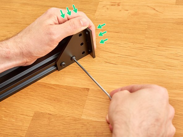
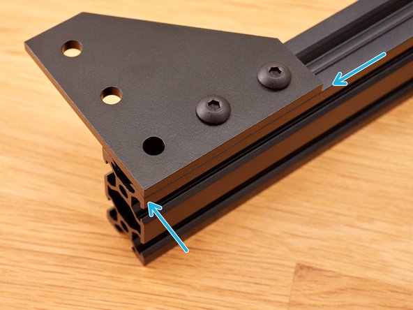
Take a joining plate and hold it against the extrusion, as shown in the 1st image. We will use it to aid in the alignment of the first joining plate
-
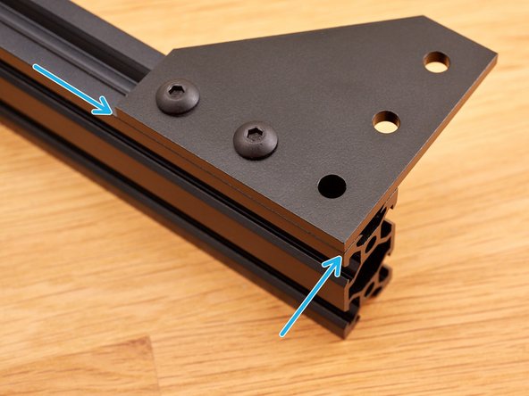
Hold the plates as shown in the 2nd image, applying pressure as shown (small green arrows) and fully tighten both M5 screws.
-
Check that your plate is flush with the face and end of the extrusion.
-
This is an important step as other steps will rely on the accuracy of this assembly.
-
-
-
Take your time with this step.
-
Repeat the instruction from Step 4, to align and attach the the joining plate at the other end of the extrusion.
-
Check that this plate is also flush with the face and end of the extrusion.
-
This is an important step as other steps will rely on the accuracy of this assembly.
-
-
-
Take your time with this step.
-
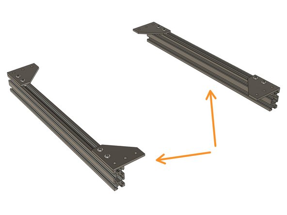
Take the other 370mm long extrusion (longest one remaining).
-
Repeat Steps 3 and 4 on this extrusion. You should now have two identical assemblies.
-
Double check that all joining plates are flush with the face and end of each extrusion.
-
This is an important step as other steps will rely on the accuracy of this assembly.
-
-
-
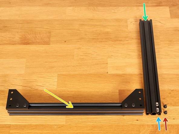
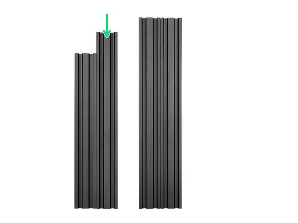
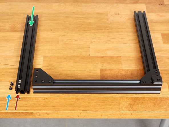
Take one of the 331mm* extrusions. (*The middle length of the five remaining extrusions)
-
Prepare the following parts:
-
1x previously completed extrusion and plate assembly
-
2x t-nuts. Slide them into the 331mm extrusion as shown in the picture.
-
2x M5x10 screws
-
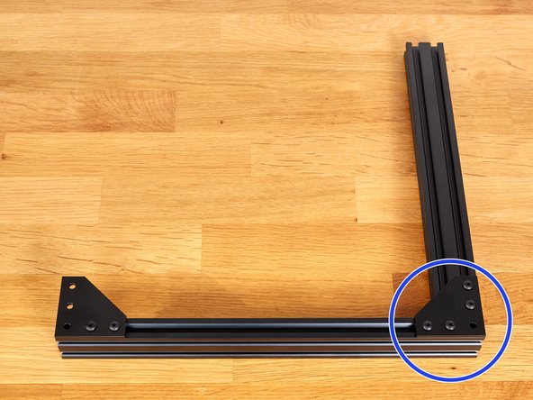
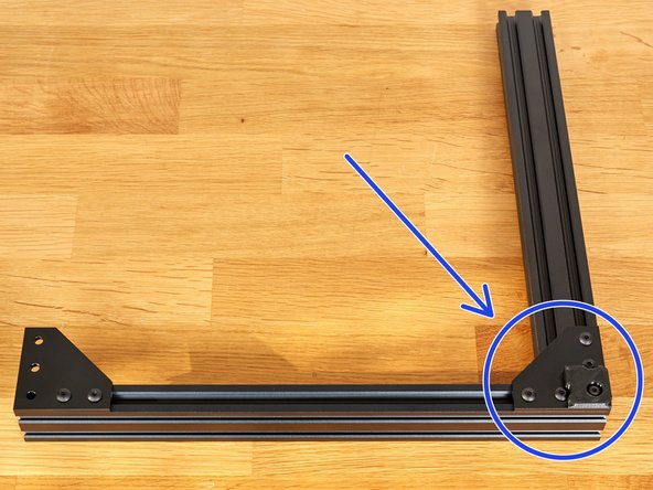
Assemble the corner, as shown, using the 2x M5 screws. Do not fully tighten these two screws!
-
-
-
Take your time with this step. It will be a reference for the rest of the assembly. A third hand might be useful, ask someone to help, if possible.
-
Make sure that you are working on a flat and level surface.
-
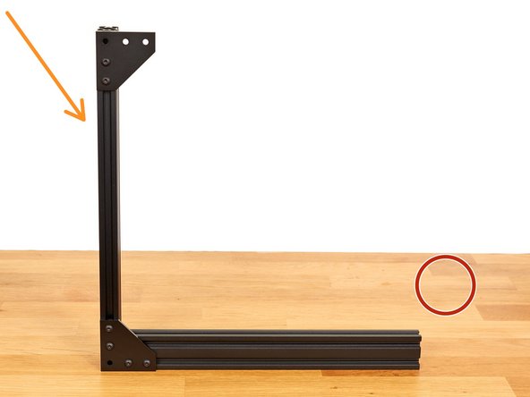
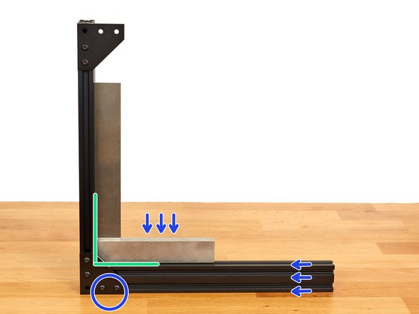
Place the assembly vertically, as shown.
-
Take care that the assembly does not fall.
-
Using a machinist's precision square, ensure that the two extrusions are perpendicular to each other.
-
Apply pressure in the directions shown and fully tighten the two M5x10 screws.
-
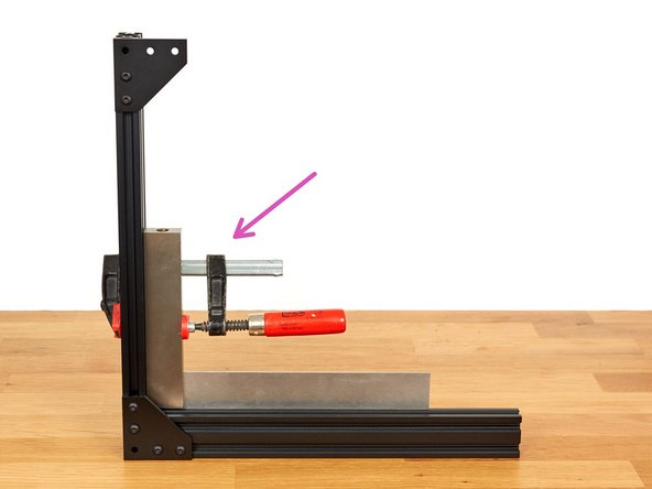
Tech tip: This step can be made easier if you have a clamp. You can then secure the thicker side of your square to the vertical extrusion as shown in the 3rd image.
-
Verify that the assembly is still square after tightening. Correct it if needed.
-
-
-
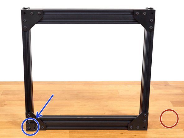
Prepare the following parts:
-
One t-nut.
-
One M5x12 screw
-
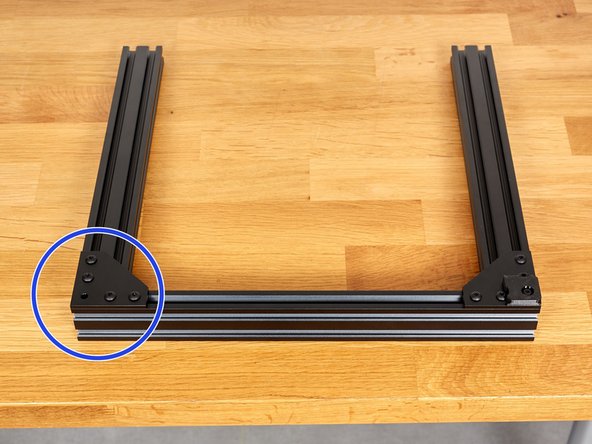
One 3D printed foot (foot.stl)
-
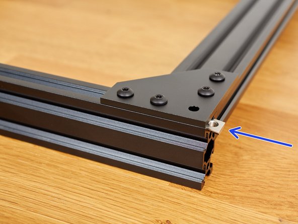
Slide the t-nut from the right side.
-
Tighten the foot with the M5x12 screw.
-
-
-
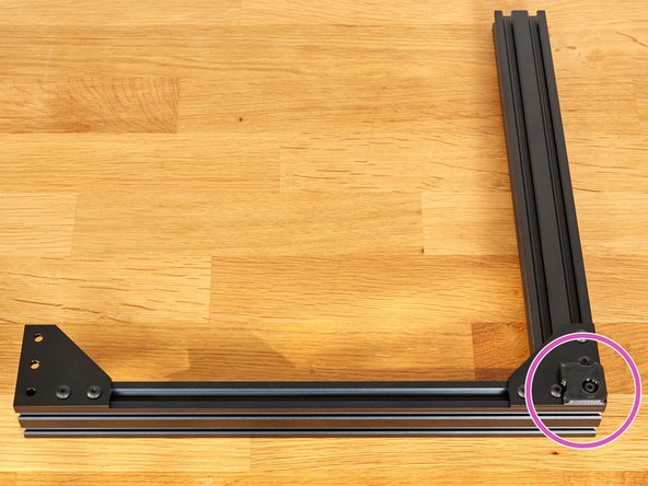
The corner with the foot is now considered as a reference. In case of doubt during the next steps, you know that this corner is perfectly square and you don't have to touch it anymore.
-
You can double check that the five M5 screws are all fully tightened.
-
-
-
Take the remaining 331mm* extrusion. (*The middle length of the four remaining extrusions)
-
Prepare the following parts:
-
2x M5x10 screws.
-
2x t-nuts. Slide them into the 331mm extrusion as shown in the picture.
-
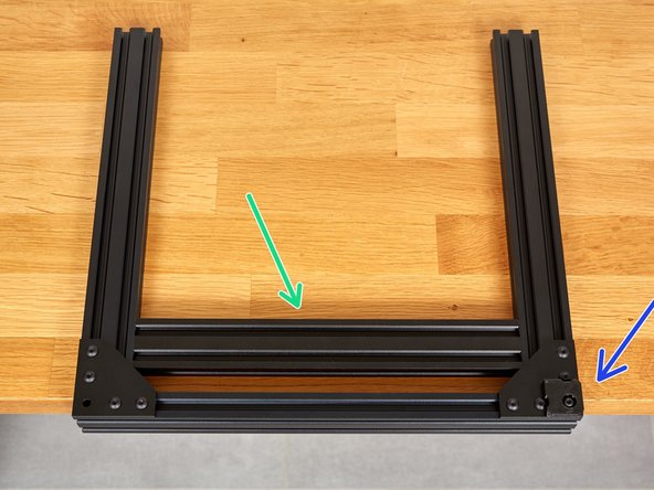
Attach the 331mm extrusion, to the assembly, with the M5 screws. Do not fully tighten them yet!
-
-
-
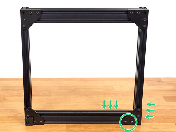
Take your time with this step.
-
Take the smallest extrusions of those remaining. It is 290mm long. It will be used as a reference, to ensure that parts are correctly spaced.
-
Place the assembly at the end of a table, as shown, so that the two 331mm extrusions lie flat on the surface.
-
Carefully place the 290mm extrusion between the other extrusions, as shown in the 2nd image.
-
Be careful that you do not scratch or permanently mark the extrusions whilst doing this.
-
Apply pressure in the directions shown and fully tighten the 2x M5x10 screws.
-
Carefully remove the 290mm extrusion and reserve it for later.
-
-
-
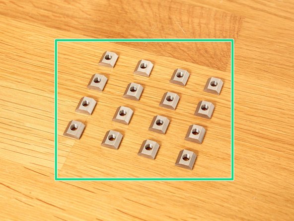
Take 16x t-nuts and for each, check that the threads are clear by inserting an M5 screw.
-
Those 16 t-nuts are captive and would require you to disassemble the Y axis of the frame, if you later find any to be defective. It is easier to check them first. You can thanks 3DMN for this handy tip :)
-
Double check that you have used the correct extrusion lengths:
-
370mm
-
331mm
-
-
-
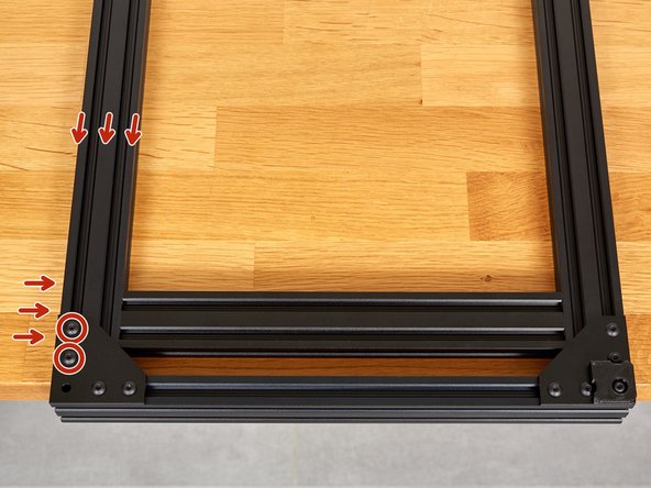
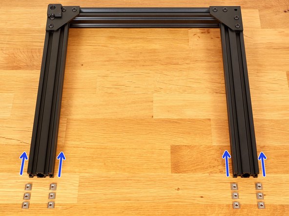
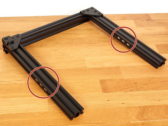
Take 12 of the previously tested t-nuts. Insert them, as shown, in both 20mm sides of the extrusions.
-
Inserts 3x t-nuts in each side (12 in total) as seen in the 2nd and 3rd pictures.
-
-
-
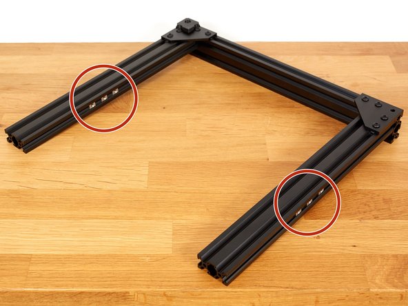
Flip the assembly. Being careful that the placed t-nuts do no fall out.
-
Take the remaining 4 t-nuts, which you previously tested, and slide them into the extrusions as shown in the image.
-
Tech tip: You can tape the t-nuts to the centre of the extrusions. This will prevent them sliding out of the extrusions during the following steps. (two small pieces of Blu Tack also work)
-
Do not place tape on the outer, 20mm, faces of the extrusions. The sides will be placed flat on the table and the thickness of the tape could affect accuracy whilst squaring the frame.
-
-
-
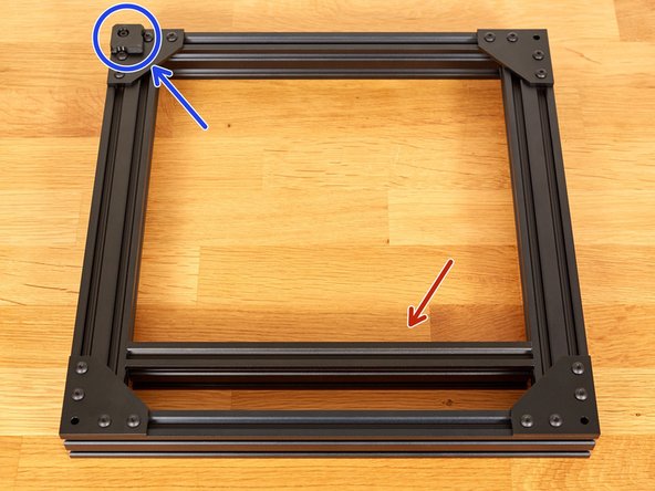
Flip the assembly. Being careful that the placed t-nuts do no fall out.
-
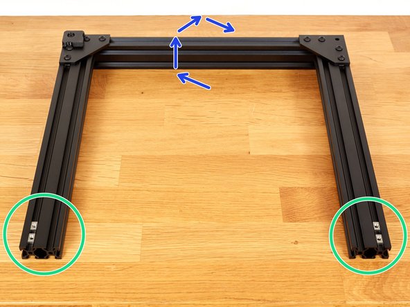
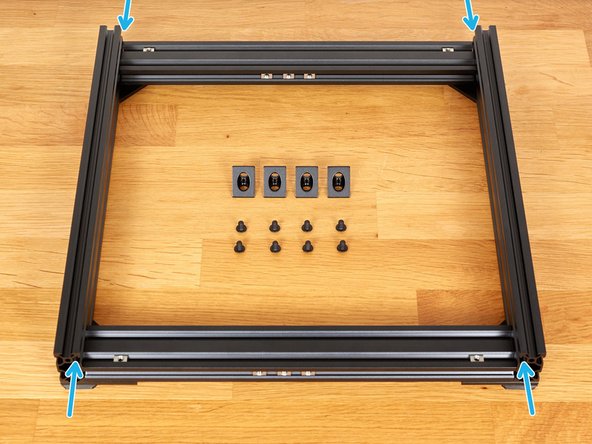
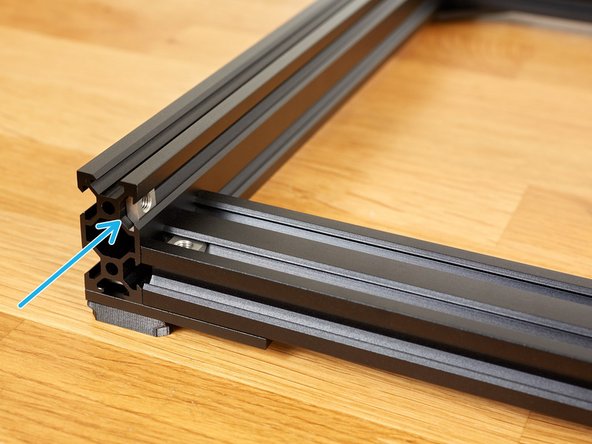
Take 4x t-nuts and insert them as shown in the 1st picture.
-
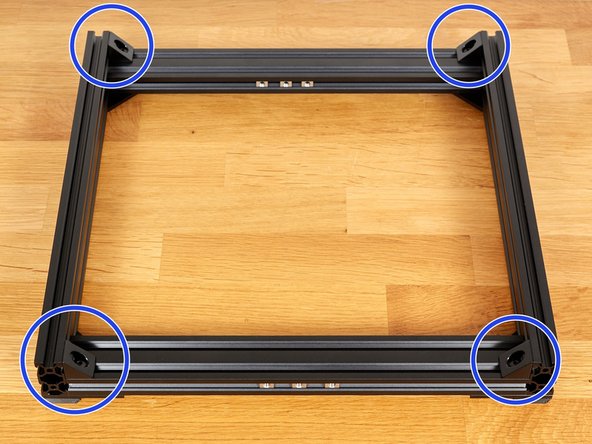
Take the second 370mm extrusion + plate assembly which you built in step 5. Attach it with 4x M5x10 screws. Do not tighten them fully yet!
-
Verify that all 12 t-nuts remain in the sides of the 331mm extrusions.
-
-
-
Take your time with this step. Ask for help from someone else if you feel the need of a third hand (please don't use one of your feet :) ).
-
Move the Y axis into to the vertical position with the 3D printed foot on the bottom left.
-
Take care that the Y axis does not fall over.
-
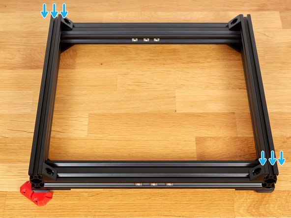
Make sure you are on a flat and level surface.
-
Apply pressure in the directions shown and fully tighten the 2x M5x10 screws.
-
-
-
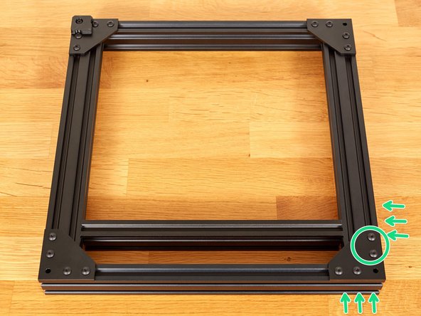
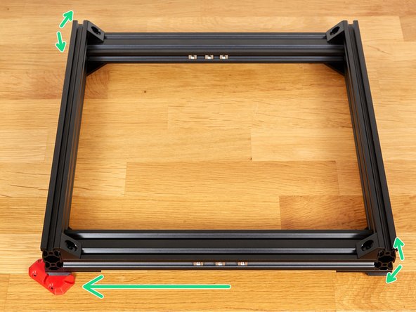
Take your time with this step. It is the last squaring operation for the Y axis :).
-
Move down the assembly with and position the 3D printed foot on the left and back.
-
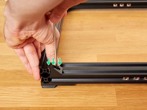
Carefully insert the 290mm extrusion in between as shown in the 1st image.
-
Be gentle or you might mark permanently the extrusions.
-
Apply pressure as shown in the image and tighten the M5 screw strongly.
-
-
-
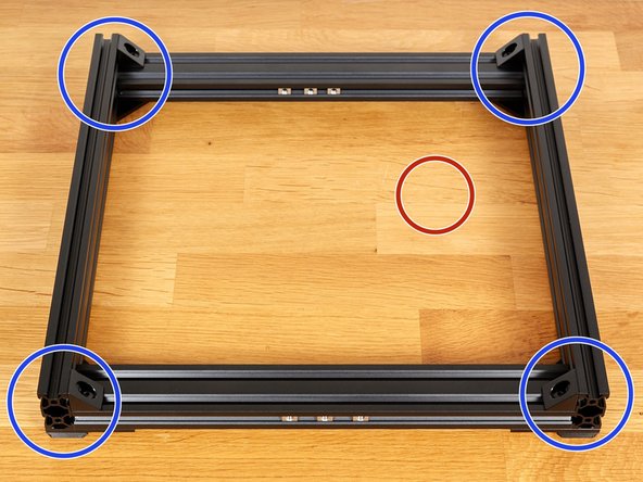
Verify that all the 6 latest M5x10 screws bolted are fully tightened.
-
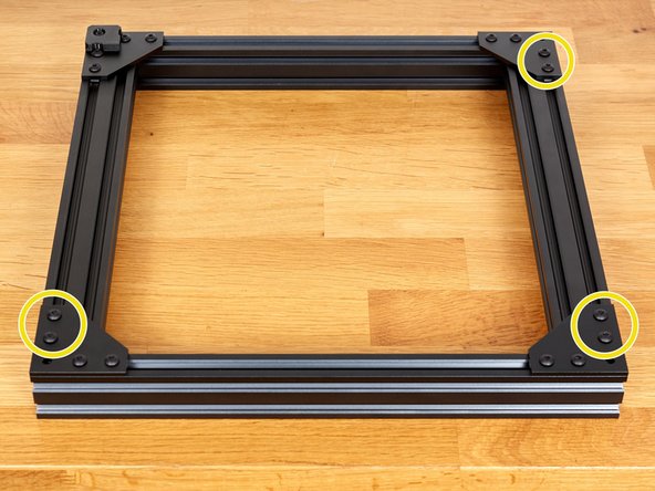
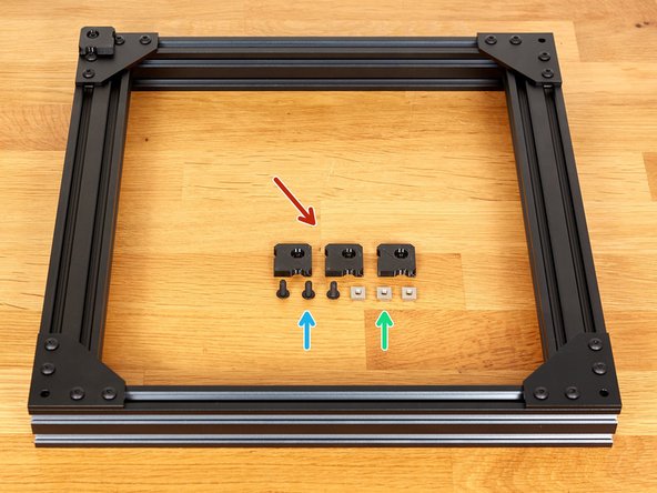
Prepare the following parts:
-
3x 3D printed feet (foot.stl)
-
3x M5x12 screws
-
3x t-nuts
-
Assemble the 3 feet using the M5x12 screws and t-nuts.
-
-
-
Flip the assembly (yes again!).
-
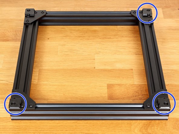
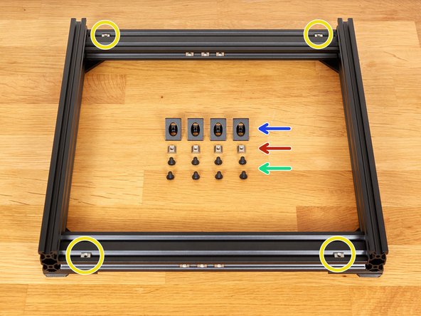
Prepare the following parts:
-
4x angle corners
-
4x t-nuts
-
8x M5x8mm screws
-
Remove the tape of the 4 t-nuts and slide them close to the vertical extrusions.
-
Insert t-nuts on the vertical extrusions.
-
-
-
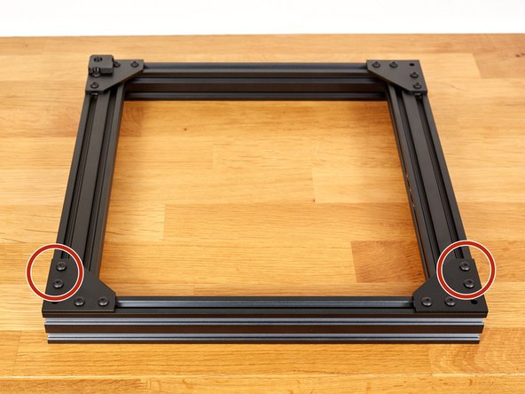
Assemble an angle corner with 2x M5x8 screws to each corners. Do not tighten them fully yet!
-
For each corners, tighten alternatively the two M5x8 screws while applying pressure as shown on the images.
-
The angle corners might twist a little the frame during tightening, we will solve this in the next step. Applying pressure while tightening reduce this.
-
Tech note: this is why the Bear frame is not using angle corners in another place.
-
-
-
Make sure you are on a flat and plane surface
-
Check that the frame is not twisted by pressing on each corners one by one.
-
If the frame remains flat you can continue to the next step.
-
If the frame is wobbling, place a 5-10mm thick object under the opposite corner as shown in the 2nd image.
-
The little up-down green arrow shows the wobbly diagonal. It might be the other diagonal for you, in this case, place the object in the bottom right corner.
-
Apply pressure on the wobbly corners on both sides at the same time. No need to apply strong pressure.
-
Now remove the thick object and verify again that the frame remains flat. If it is still wobbling, repeat those steps until it remains flat.
-
If this is still not working double check if your surface is flat. If this is the case then unscrew a little the angle corners and repeat previous step and then current one.
-
-
-
Congratulations you have finished the hardest part of the assembly :-)
-
Got to the next chapter: 04. Z axis frame
-