Difficulty
Moderate
Steps
11
Time Required
- 6. Z axis motion 11 steps

In Progress
This guide is currently being written. Reload periodically to see the latest changes.

Private
This guide will not appear in search results and can only be viewed by team members!
-
-
If you haven't check the Z axis parts during the preflight check then you should do it now or you might have problem during this chapter.
-
Note that in this chapter you will see images of MK3(S) Y carriage but all steps are exactly the same for MK2(S) and MK2.5(S).
-
-
-
Make sure you have removed the original lead screw covers as specified in the preflight check and disassembly guide
-
This is not optional, the original lead screw covers are not compatible with the Bear Z motor mounts.
-
Screw the Bear z_leadscrew_caps on both motors.
-
The z_leadscrew_caps should screw down to the Z motor but should not be tight at all. Make sure the lead screw can turn freely.
-
-
-
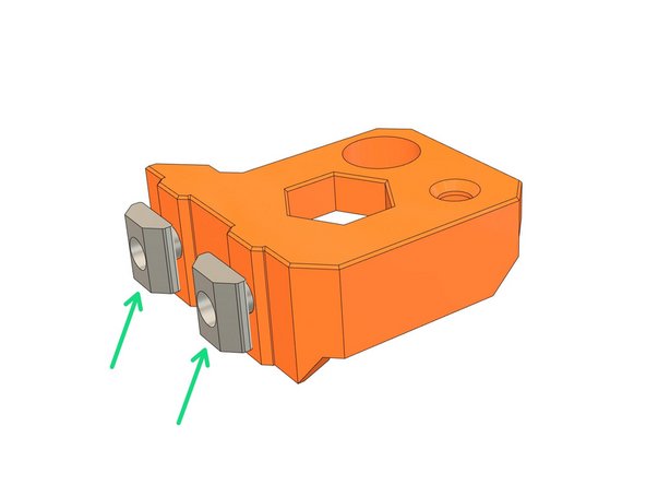
Insert 2x M5x10 screws in the z_motor_mount.
-
Engage 2x t-nuts on the M5 screws (1-2 turns) and place them vertically.
-
Repeat with the remaining z_motor_mount.
-
-
-
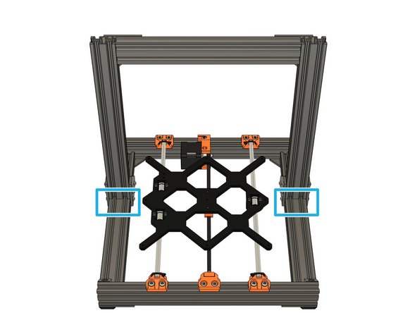
Make sure this section is clean of dust, it will be used as reference for the z_motor_mounts.
-
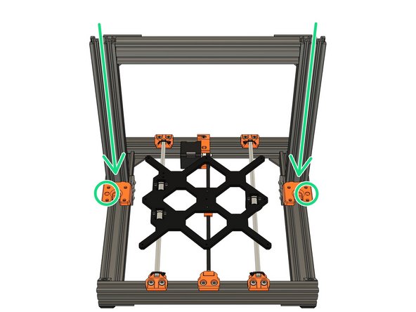
Slide the z_motor_mount from the top of the frame. Note the orientation, the hole for the Z smooth rods should face outside the frame
-
Double check the orientation of your z_motor_mount or it will make the next steps impossible.
-
-
-
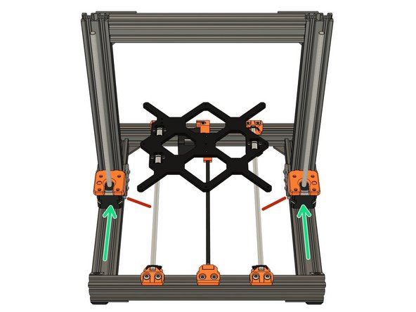
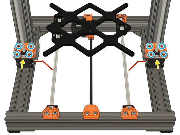
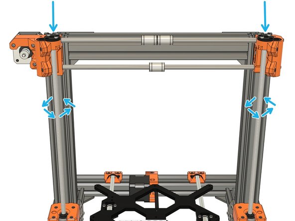
Slide the Z motors in the z_motor_mounts. The motor cable should be oriented inside the frame (red lines on the images).
-
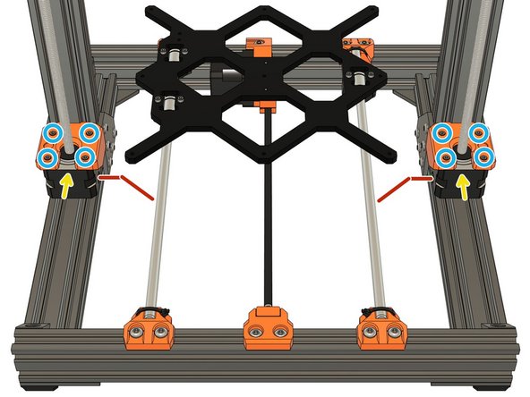
Secure the Z motors in place with 8x M3x10 screws (reused from your original Prusa). Press the motor in the direction of the yellow arrows while tightening incrementally the screws.
-
Note that the previous z_motor_mounts of Bear 2.0 was using M3x12 screws and they will be too long for these new mounts.
-
Check the orientation of your motor cables.
-
-
-
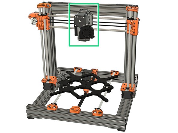
In this step we prepare the X axis to later assemble it on the Z axis.
-
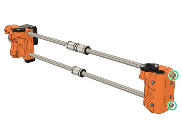
If you are using the Bear X axis or Original Prusa MK2(S)/MK2.5(S) X axis you need to unscrew a little the smooth rods screws (approx. 2mm).
-
If you still have the X carriage (or extruder) in place you must release the belt tension in X axis.
-
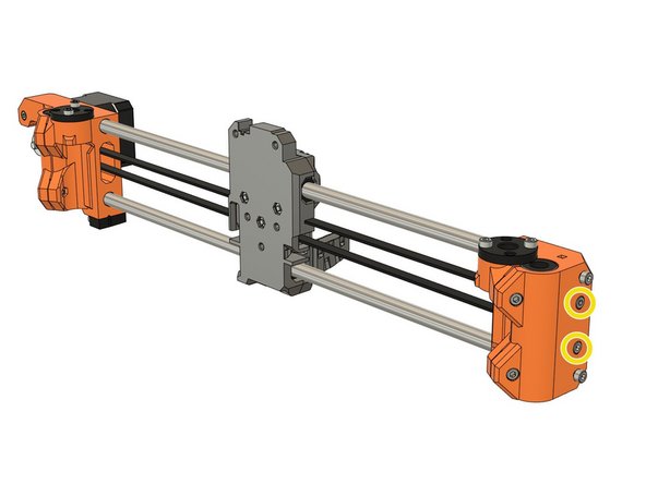
Bear extruder and X axis (BearExxa), BearMera of Bear X axis with Bondtech extruder: release tension using the belt tensioning screws.
-
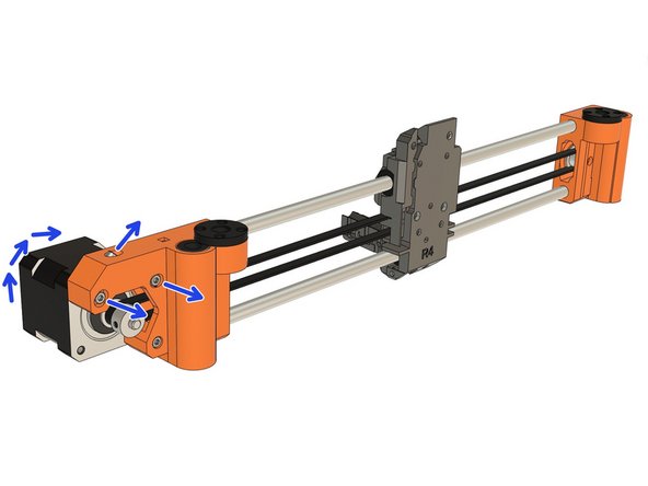
Original Prusa MK3(S): remove the 2x top motor screws and release tension of the screw on top of the arm. Then rotate the X motor.
-
Original Prusa MK2(S) or MK2.5(S): remove the 2x top motor screws and rotate the X motor.
-
Be careful, if you still have the X carriage (or the extruder) in place you will have to disassemble the Z motors to insert the X axis in the next step.
-
-
-
Be careful with this step as you might damage the lead screw nuts (black nuts on the X ends).
-
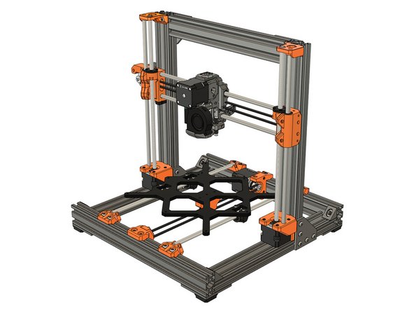
Place the X axis on top of the Z lead screws. Carefully rotate by hand the Z lead screw to engage and move down the X axis.
-
Be very careful, never force on the lead screw nuts or you might damage them.
-
Rotate the lead screws in synchronization.
-
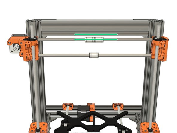
Continue to rotate the Z lead screws simultaneously until you can align the top X smooth rod with the bottom of top Z axis extrusion.
-
Verify the X axis is parallel and make correction if necessary.
-
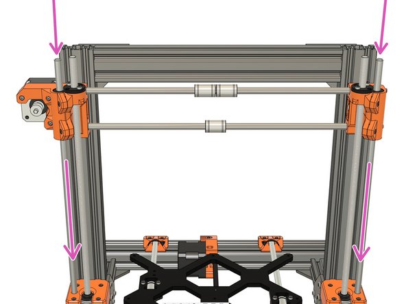
Very gently slide the two Z smooth rods (320mm long) down to the Z motors. The smooth rods must be fully inserted until they touch the Z motors (you can hear a "metallic click" when you reach the motor).
-
Verify the Z smooth rods are fully inserted down to the Z motors. This is very important as it might affect the alignment of your X axis later.
-
-
-
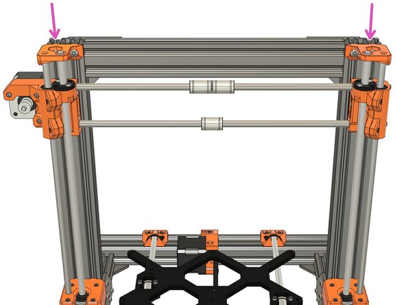
Insert 2x M5x10 screws in one of the z_top.
-
Engage 2x t-nuts on the M5 screws (1-2 turns) and place them vertically.
-
Repeat with the remaining z_top.
-
-
-
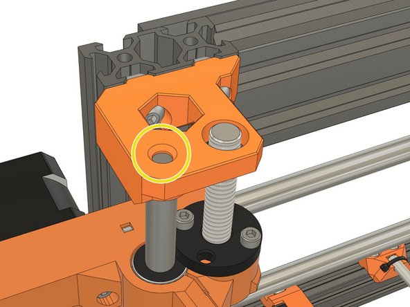
Install the z_tops on top of the Z axis. T-nuts must go into the extrusion's grooves and the smooth rods in the smallest of the two front holes.
-
You must press down the z_tops until the smooth rod is touching on top of the hole.
-
This is very important as it might affect the alignment of your X axis later.
-
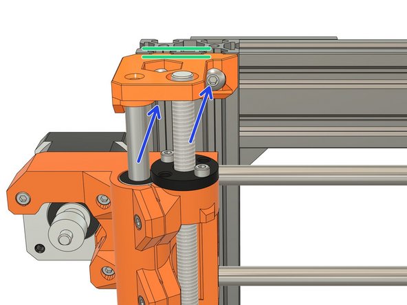
Make sure the z_tops are parallel to the top of the extrusion
-
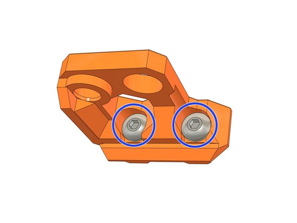
Tighten the 2x M5x10 screws.
-
Double check that the smooth rods are fully inserted in the z_tops.
-
-
-
In this chapter you will have to follow external guides. As the Bear frame supports different extruders and X axis it would make this guide too long and hard to follow. Thank you for your comprehension :)
-
Reinstalll the extruder on the X axis by following the external guide(S) according to your extruder and X axis:
-
BearExxa (Bear extruder and X axis): start with 3. Extruder, then 4. Extruder and X axis assembly up to step 10 and finish with 5. Final adjustments and calibration up step 8.
-
BearMera (E3D Hemera): start with 3. BearMera extruder up to step 14, and then 4. Adjustments.
-
Bondtech on Bear X axis: follow our guide here.
-
Original Prusa extruders installation guides: MK3S, MK2.5S, MK3 (spiral wrap), MK3 (textile sleeve), MK2.5 (spiral wrap), MK2.5 (textile sleeve), MK2S.
-
Bondtech extruder on original Prusa X axis: choose the guide corresonding to your extruder on support.bondtech.se/c/Prusa.
-
-
-
Congratulations you have finished this chapter :-)
-
Go to the next chapter: [invalid guide link].
-