
-
-
Inserting Hex Nuts: To assure that hex nuts are properly seated, do the following:
-
Add a washer to the screw, to avoid damaging the printed part.
-
Insert the screw through the hole on the opposite side to the hexagonal cavity.
-
Thread the hex nut onto the screw and tighten the screw.
-
Ensure the hex nut is aligned with the hex cavity while tightening.
-
When the nut is fully seated, remove the screw being careful not to dislodge the nut.
-
Inserting Nyloc Nuts: You can use the same method as used for the hex nuts.
-
Inserting Square Nuts: They tend to fall out of the piece holding them is inverted. After they are inserted, check that they are properly seated by inserting a screw to engage the nut.
-
-
-
extruder_body
-
extruder_cover
-
extruder_idler
-
fs_lever
-
nozzle_fan_duct (with print support removed)
-
filament_sensor_cover
-
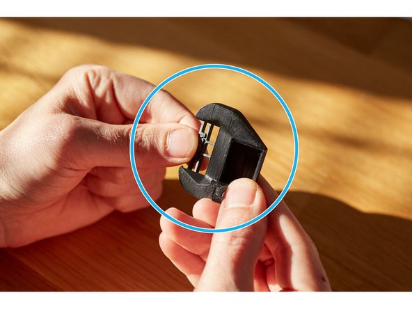
hotend_collet_clip
-
-
-
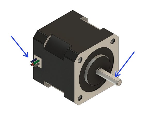
Locate the extruder motor so the wires face to the left. Rotate the shaft so that the flat side is facing up.
-
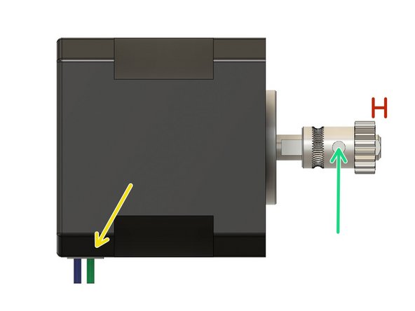
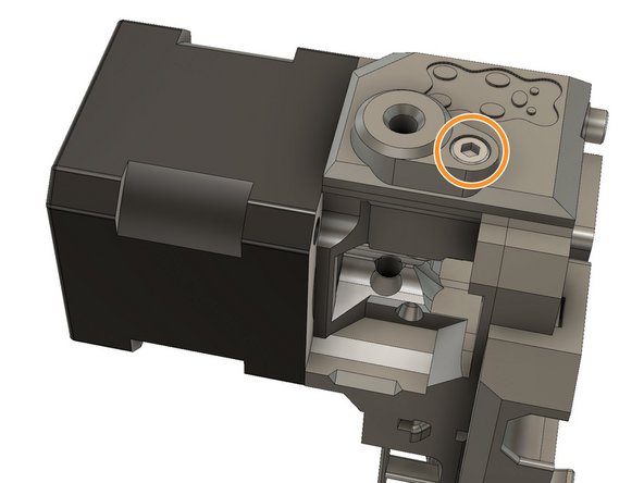
Mount the Bondtech pulley on the extruder motor shaft so that the geared portion is furthest from the motor body. Make sure that the set screw is in contact with the flat portion of the shaft.
-
The motor shaft should protrude from the pulley by approximately 1mm.
-
Secure the set screw to avoid the gear moving. We will fine tune the position later.
-
Verify the orientation of the motor cables.
-
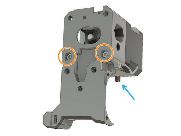
Secure the extruder motor to the extruder_body using two M3x25 screws.
-
Verify the orientation of the motor cables.
-
-
-
Insert three M3 hex nuts
-
Insert two M3 nylock hex nuts
-
Make sure those nuts are fully set as you will not be able to remove them once the extruder body is assembled.
-
-
-
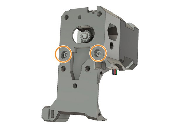
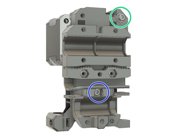
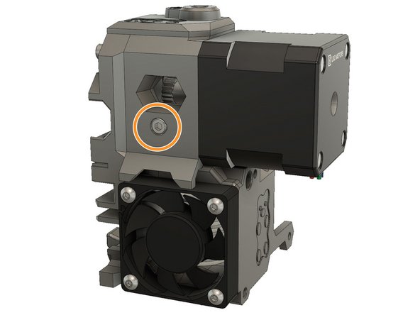
Verify that the M3x25mm screws are snug
-
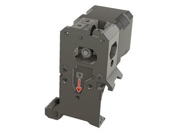
Slide a M3 square nut into the extruder_body.
-
Use a M3x10 screw to attach the extruder_body to the x_carriage.
-
Use a M3x40 screw with a M3 washer to attach the extruder_body to the x_carriage.
-
Verify that extruder_body and x_carriage are correctly aligned. Use the M3x10 and M3x40 screws to adjust, if necessary.
-
-
-
Verify that the filament_sensor_lever and the filament sensor pocket on top of the extruder_body do not have any strings and are printed well. Clean up if necessary.
-
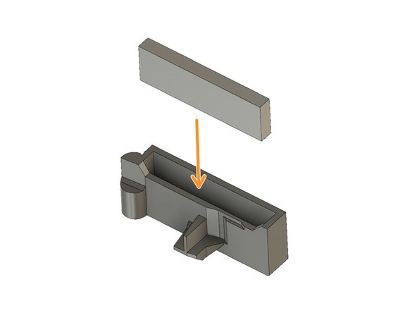
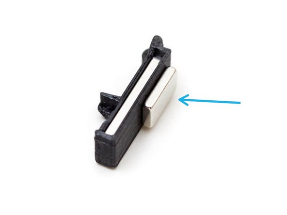
Insert the longer magnet (20x6x2mm) inside the filament_sensor_lever.
-
Place the smaller magnet (10x6x2mm) so it is attracted to the filament_sensor_lever. The smaller magnet should be on the flat side of the lever.
-
Remove the smaller magnet from the filament_sensor_lever and insert it with the same orientation into the extruder_body. DO NOT insert the filament_sensor_lever yet.
-
Verify that the smaller magnet is fully inserted into its cavity.
-
-
-
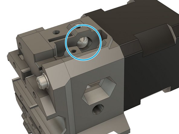
Insert the steel ball in the dedicated pocket of the extruder_body.
-
Verify that the steel ball is rolling smoothly inside its pocket.
-
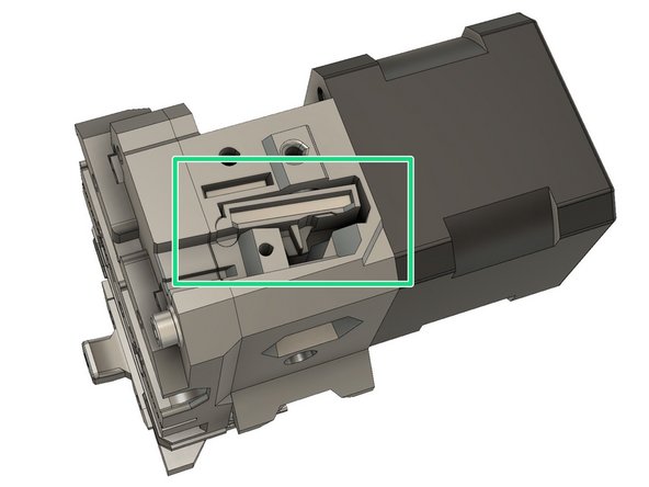
Insert the filament_sensor_lever.
-
You can use a flat screwdriver to keep the steel ball in its pocket when inserting the filament_sensor_lever.
-
Test if the filament_sensor_lever is moving correctly with a piece of filament.
-
-
-
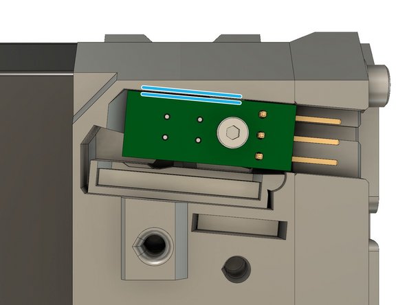
In order to avoid electrostatic discharge to the filament sensor, touch something metallic that is linked to the ground. Like pipework or a faucet.
-
Carefully secure the Prusa IR sensor with a M2x8 screw. Do not over-tighten.
-
Adjust the Prusa IR sensor to make sure that it is parallel to the border of the pocket. Finish tightening the screw; it only needs to be tightened sufficiently to hold the sensor in place
-
-
-
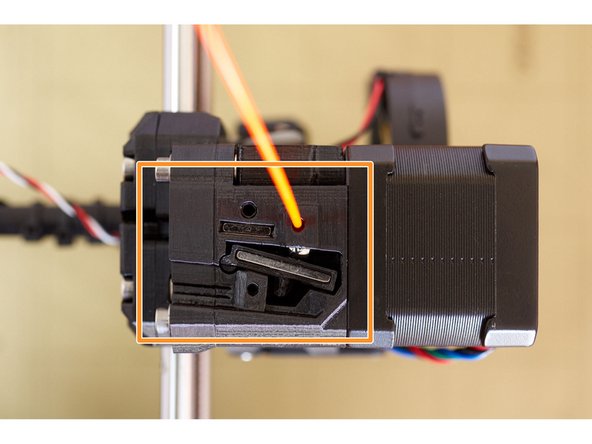
Verify with a piece of filament that the filament_sensor_lever is working smoothly.
-
-
-
Install and secure the filament_sensor_cover with a M3x10 screw.
-
-
-
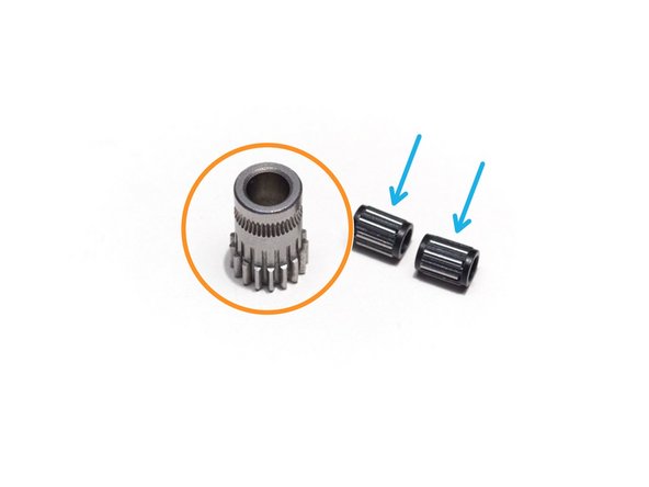
Locate the Bondtech idler gear. It is the one that has NO set screw.
-
Lubricate the needle bearings with a dab of lithium based grease
-
Slide the two Bondtech needle bearings into the Bondtech idler gear.
-
-
-
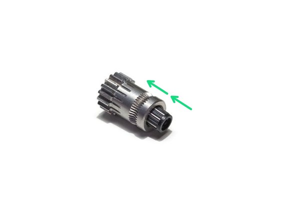
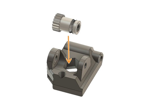
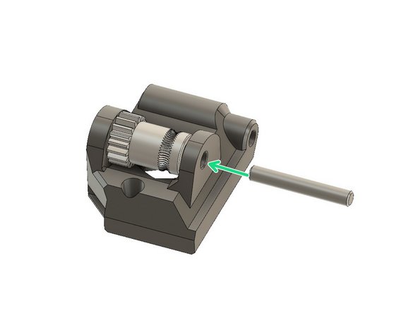
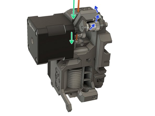
Place the idler gear into the extruder_idler. Note the orientation of the teeth.
-
Make sure that both needle bearings are still inserted in the idler gear.
-
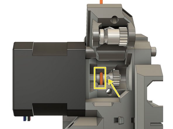
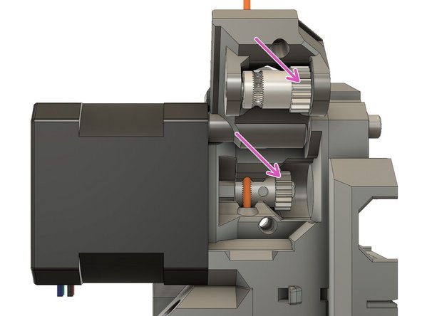
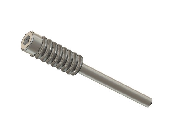
Insert the shaft from the direction shown in the diagram. Fully insert the shaft, it should be flush with the printed part or the the idler will not close properly.
-
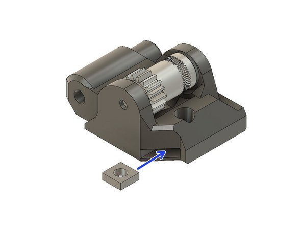
Insert a square nut in the lateral pocket.
-
Double check the orientation of the gears.
-
Double check that no needle bearing has fallen out during these steps.
-
-
-
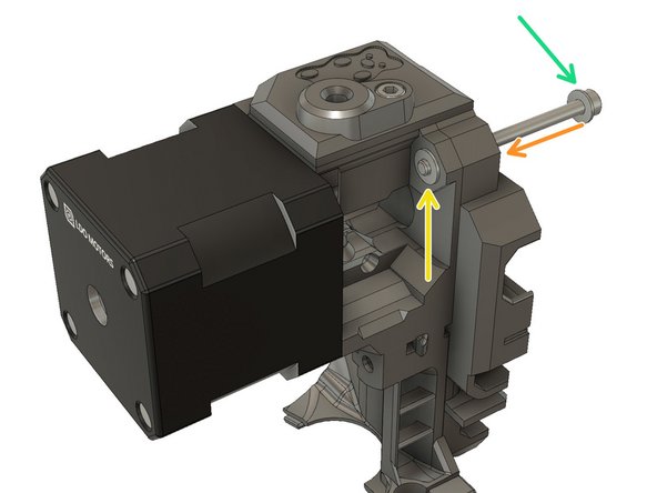
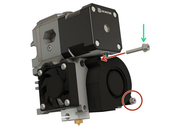
Slide a M3 washer on a M3x40 screw.
-
Insert the screw into the top, left hole of the x_carriage, until it protrudes just enough for you to place a M3 washer on it.
-
Carefully place a M3 washer on the end of the screw.
-
Carefully slide the extruder_idler into the opening, taking care not to displace the M3 washer and insert the screw to act as the hinge for the idler door.
-
Gently tighten the screw into the extruder motor, the extruder_idler must rotate freely.
-
-
-
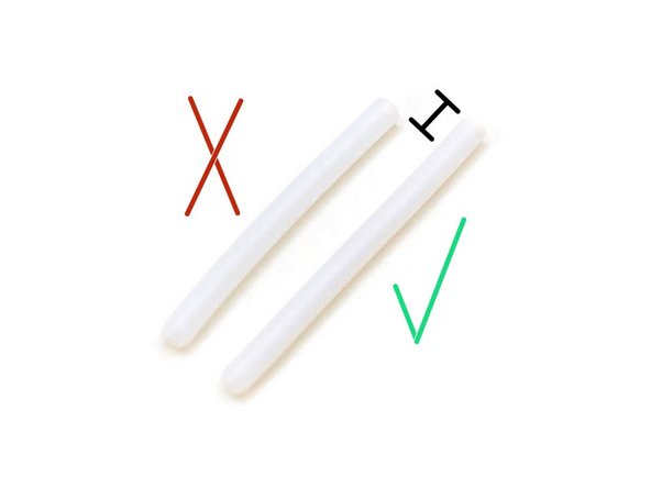
The Bear extruder uses a PTFE tube length of 50mm. It is the same PTFE tube used for MK2S, MK2.5 (non-S) and MK3 (non-S). The original Prusa MK2.5S or MK3S extruder is using a PTFE tube length of 44.2mm which will be too short for the Bear extruder.
-
You should have prepared the PTFE tube during guide 1. Preflight check and disassembly. Make sure you have followed those steps.
-
-
-
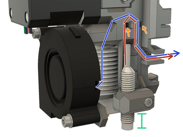
Hotend wires are not visible on these images. Use the heatblock for correct orientation of the hotend.
-
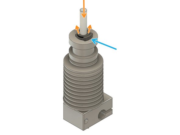
Verify your PTFE tube is 50mm long.
-
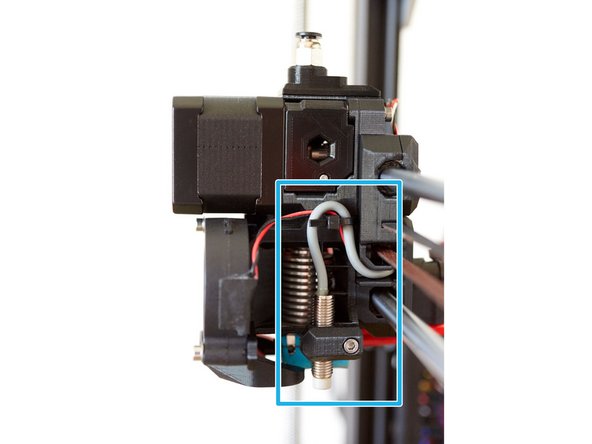
Push the collet (black plastic part) down and fully insert the PTFE tube. Whilst pressing the PTFE tube into the hotend, lift the collet upwards, to lock the PTFE tube in place
-
Insert the hotend_collet_clip. This prevents the collet from loosening and keeps the PTFE tube locked in place.
-
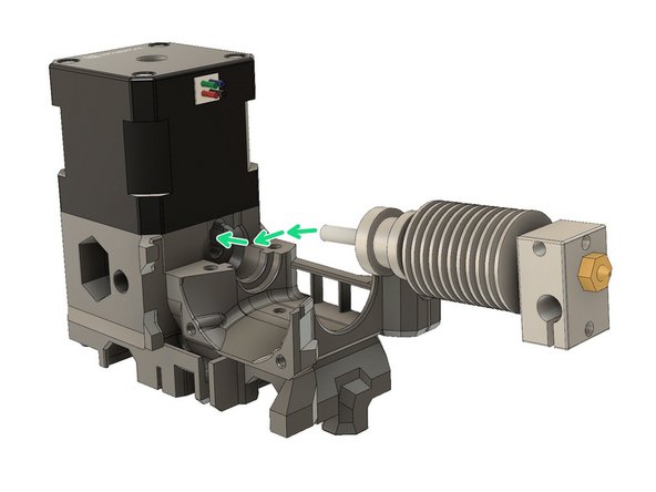
Insert the hot end into the extruder_body with correct orientation of the heater and thermistor wires.
-
Note the position of the heater and thermistor wires.
-
-
-
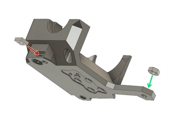
Insert one M3 square nut
-
Insert one M3 hex nut
-
Insert one M3 hex nut
-
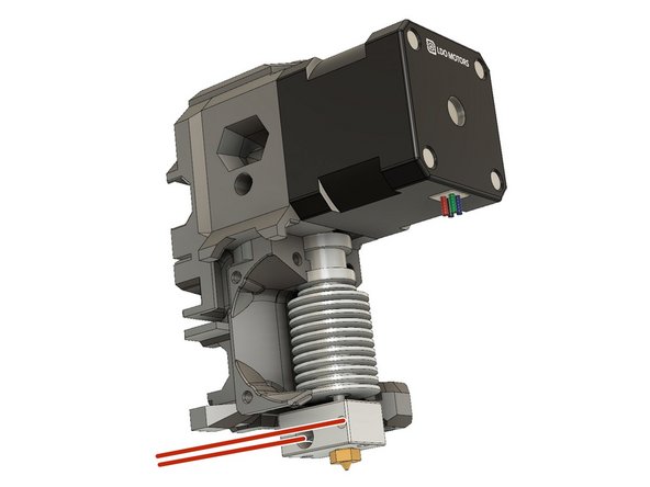
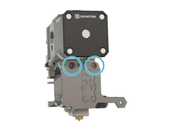
Insert two M3x40 screws and tighten them alternately to lock the hotend in place
-
Check that the hotend has not rotated, is perpendicular to the extruder body and is correctly oriented. Adjust if necessary.
-
-
-
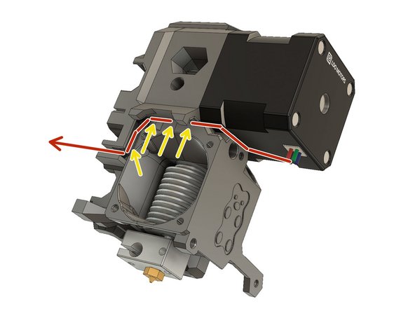
Carefully route the motor wires as shown in the figure.
-
Verify that the wires sit correctly in the channel.
-
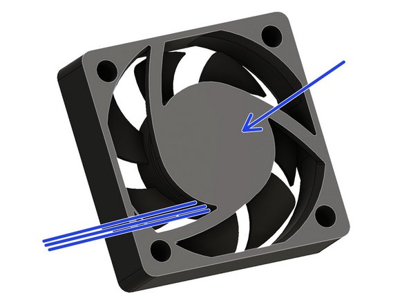
This surface will be touching the extruder_body. It is the side with the manufacturers label on it. The wires come out from this side and the fan should be oriented so that they point towards the rear of the extruder.
-
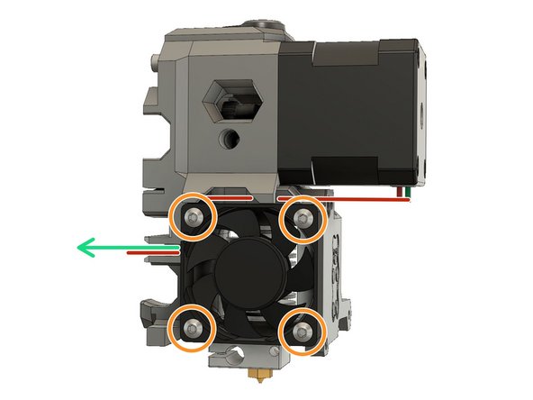
Carefully route the hotend fan wires in the channel of the x_carriage.
-
Attach the hotend fan with four screws. Follow the screw type according to your hotend fan:
-
Sunon & Delta : M3x16 button head screws
-
Noctua : M3x14 socket head screws
-
Check that no wires are pinched. Check the orientation of the hotend fan, the air should be blowing over the hotend heatsink. On the edge of the fan body, there are usually two arrows, indicating the direction of rotation and direction of flow. Ensure that the arrow indicating flow is pointing in towards the hotend.
-
-
-
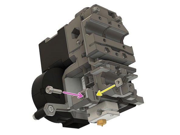
Open the extruder_idler
-
Insert a piece of 1.75 mm filament through the extruder_body into the PFTE tube.
-
Center the filament on the drive teeth carefully, using the Bondtech set screw.
-
Tighten the set screw. Don't tighten too much as you will damage the thread.
-
Remove the filament.
-
This is a good time to put a dab of lithium based grease on the gears. Make sure that you do not put any grease on the drive teeth.
-
-
-
Make sure that you have completely removed the filament from the extruder_body.
-
Slide an extruder spring onto a M3x40 screw.
-
Close the extruder_idler door.
-
Slide the screw with the extruder spring into the extruder_body.
-
Tighten the screw into the extruder_idler until the head is flush with the surface of the body.
-
If you have trouble closing the extruder_idler, try rotating the Bondtech idler gear, with a finger, to ensure that the gears are meshed.
-
-
-
Place a square nut in the extruder_body for the pinda_mount.
-
Slide a M3x10 screw into the pinda_mount and engage the square nut, but do not tighten yet.
-
Insert the PINDA into the mount so that the sensor end is approximately 12mm below the bottom of the pinda_mount. Tighten the screw just enough to keep the PINDA from falling out. The optimum PINDA position will be adjusted later.
-
Route the PINDA wires as indicated
-
Route the print fan wires as indicated
-
Secure the wires with a zip tie. Be sure to leave some slack since the PINDA position will need to be adjusted later.
-
This is the preferred example of how the PINDA and print fan cables should be wired.
-
-
-
Make sure you have broken the support for the nozzle_fan_duct.
-
Insert the print shroud. If necessary, slightly unscrew the print fan.
-
Use an M3x10 screw to attach the shroud and secure the print fan.
-
-
-
Congratulations you have finished this chapter :-)
-
Go to the next chapter: 4. Extruder and X axis assembly
-


Cancel: I did not complete this guide.
23 other people completed this guide.
