
-
-
Insert four M3 square nuts in the x_carriage_back
-
Tweezers are handy to insert those square nuts.
-
If you have trouble inserting the top left square nut, slowly unscrew the M3x40mm screw until you can insert the nut.
-
-
-
Clamp the extruder on the top and bottom linear bearings of the X axis
-
Make sure to not let fall down the extruder until it is secured, keep an hand on it.
-
Make sure all cables, except the hotend cables, are running on top of the bottom smooth rod (between two X smooth rods). The hotend cables should stay under the bottom smooth rod.
-
Clamp the top of the x_carriage_back.
-
Secure it with two M3x10 screws in the top holes. Don't tighten them yet!
-
Finish securing it with two M3x18 screws in the bottom holes. Don't tighten them yet!
-
Alternately tighten the four screws while moving the extruder. Don't over-tighten them.
-
-
-
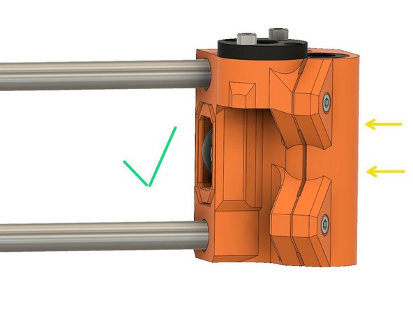
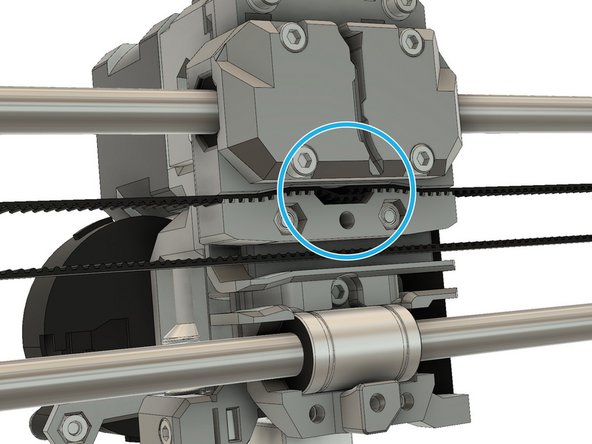
Adjust the two x_end_idler screws so that the x_end_idler_tensioner is flush with the x_end_idler, as shown in the first image.
-
Verify that the x_end_idler_tensioner is not recessed into, or protruding out of, the x_end_idler. It should not look like the second or third image.
-
-
-
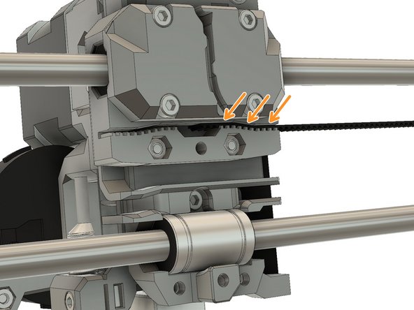
Slide one end of the 2GT drive belt into the right side of the x_carriage.
-
If you have trouble inserting the belt, it might be due to an extrusion multiplier issue (over-extrusion) or due to the use of a non-2GT belt (GT3 for example). Check the step 6 of Preflight check and disassembly chapter for more details.
-
Verify that the belt is fully inserted into the slot and that it extends into the enlarged center space.
-
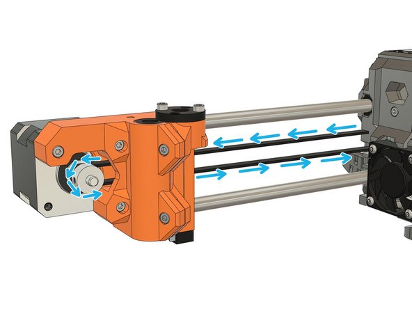
Route the drive belt through the x_end_motor, around the drive pulley and back out through the x_end_motor.
-
-
-
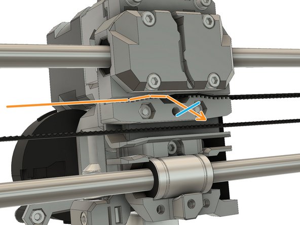
Route the belt through the x_carriage.
-
Continue to route the belt around the idler of the x_end_idler_tensioner and go back in the direction of the x_carriage.
-
If you have difficulties to pass the belt around the idler you can tape the belt end with the end of a zip tie. Then, feed the zip tie into the idler.
-
To finish routing the belt, partially insert the belt into the x_carriage
-
The belt should have almost no tension, it will be adjusted later.
-
Trim the belt to length, leaving a few teeth to extend into the center space. Finish by fully inserting the belt into the x_carriage
-
Verify that the belt is fully inserted into the slot and that it extends into the enlarged center space. You can use tweezers or a small screwdriver to ensure that the belt is pushed fully into the slot.
-
Verify that no cable is pinched by the belt.
-
-
-
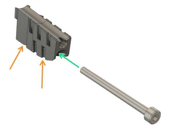
Hold cable_guide_back_a and cable_guide_back_b together
-
Slide a M3x40 screw through them
-
Screw the M3x40 screw into the x_carriage
-
The M3x40 screw should be at a slight angle to the horizontal while you are tightening it.
-
-
-
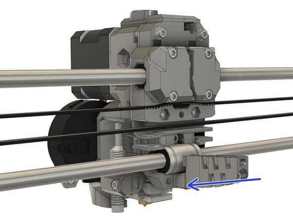
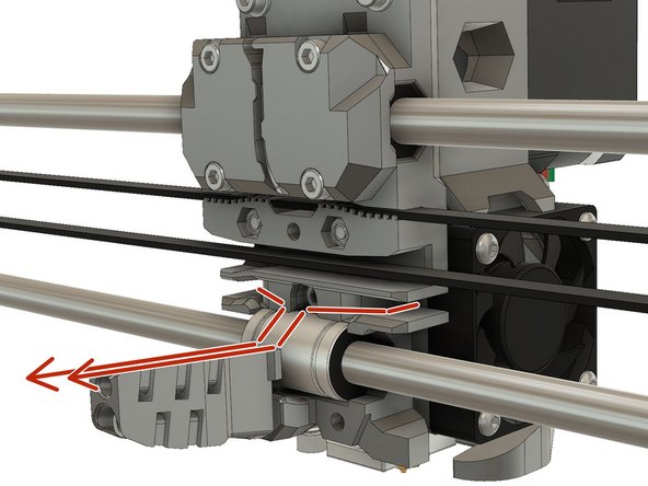
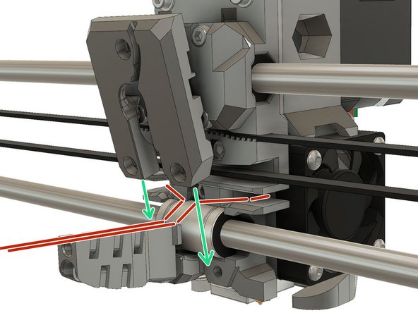
Carefully gather the Extruder motor, hotend fan, PINDA and nozzle fan cables, into a single bundle. Make sure that the cables are routed through the channels provided for them, as shown in the first image
-
Slide the bottom of the x_carriage_back carefully over the cable bundle. Ensure that the cables are in their channels and that none of the cables are pinched against the x_carriage or x_carriage_back.
-
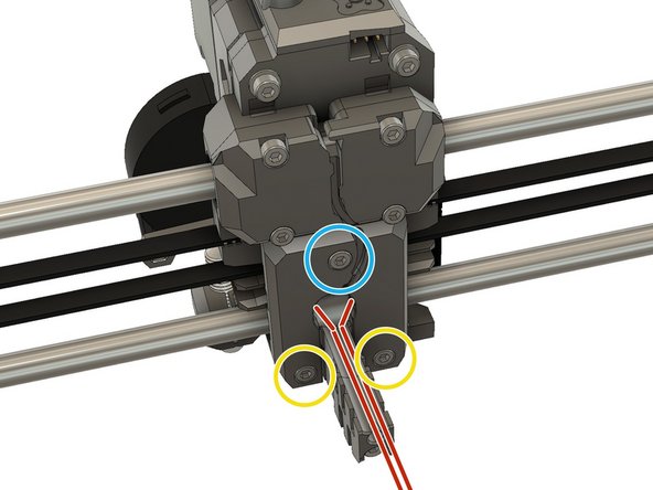
Secure the bottom of the x_carriage_back with one M3x18 screw,
-
and two M3x10 screws.
-
-
-
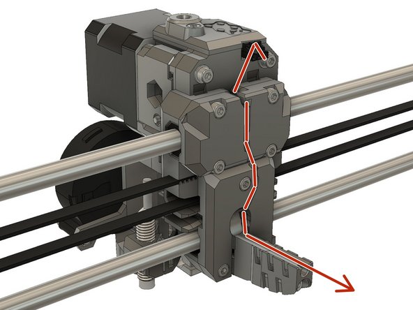
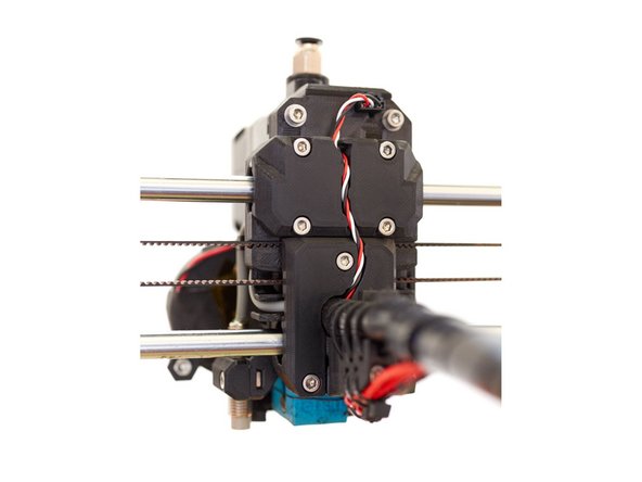
Plug the filament sensor cables into the filament sensor connector. The red wire of the cable should be on the left (on the PSU side), when connected to the filament sensor.
-
Route the filament sensor cable through the channel in the x_carriage_back.
-
Create a small loop close to the filament sensor connector. This is to reduce potential stress on the cable, caused by movement of the extruder.
-
-
-
If you do not have the textile sleeve, these instructions apply to the plastic spiral wrap as well.
-
The 3mm nylon filament can also be a piece of 2.85mm nylon filament for 3D printers.
-
The textile sleeve should be 13mm outside diameter and 490mm long.
-
Insert the 3mm nylon filament into the end of the cable_guide_back.
-
The nylon filament should slide in at least 10 mm. If you have trouble inserting it, the nylon filament end may need to be tapered with a diagonal cut and/or needle nose pliers may need to be used to get a better grip.
-
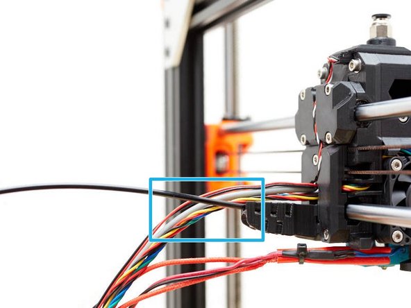
Wrap a few centimetres of the textile sleeve around all of the cables coming out of the x_carriage_back. Do not wrap the nylon or hotend cables.
-
Slide the textile wrap up to the x_carriage_back and make it as tight as possible around the cables.
-
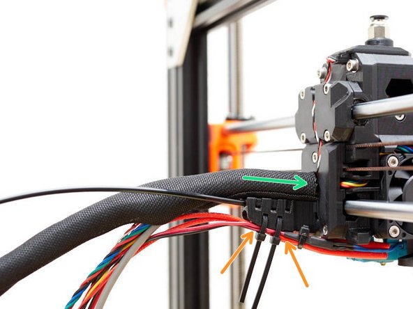
Insert two zip ties, through the bottom of the cable guide and use them to secure the hotend cables. Take care to position the zip ties as shown.
-
-
-
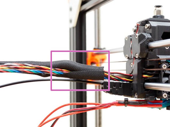
Gather the extruder cable bundle, the 3mm nylon stiffener and the hotend cables together.
-
Continue to wrap the textile sleeve around all of the cables right up to the end.
-
Trim the two bottom zip ties.
-
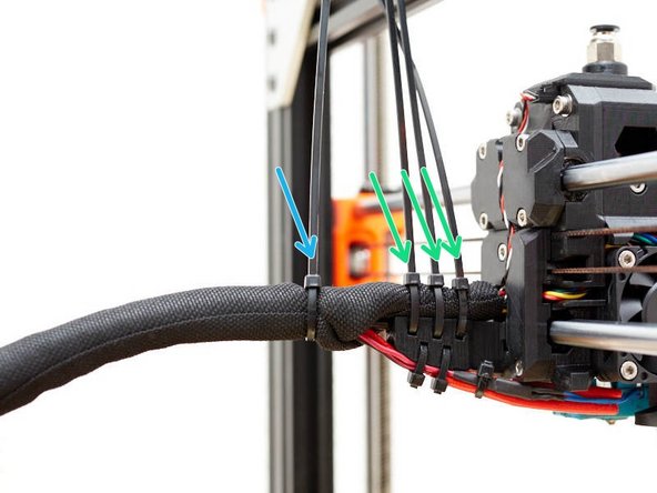
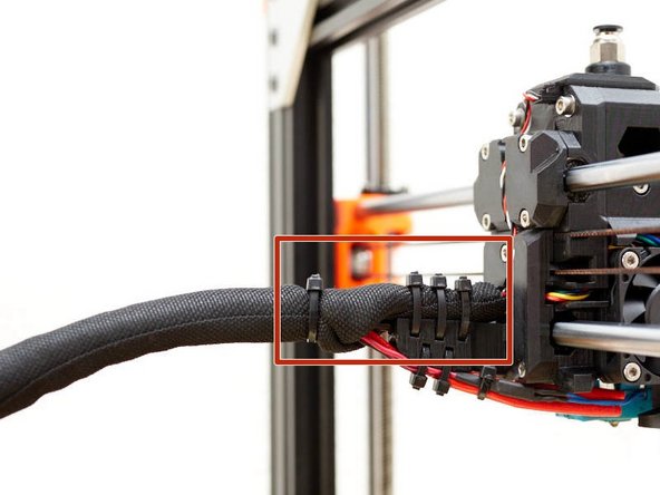
Add 3 zip ties to secure the textile sleeve to the top of the cable_guide_back. Ensure that the ties are arranged as shown.
-
Add one more zip tie after the junction with hotend and nylon cables.
-
Trim the zip ties.
-
It is important that the heads of the zip ties are arranged, so that they are at the top or bottom of the cable bundles, otherwise they may interfere with the full travel of the extruder along the x-axis.
-
-
-
Follow the original Prusa manual to connect your extruder cables on the Mini-Rambo / Einsy-Rambo:
-
-
-
-
-
Congratulations you have finished this chapter :-)
-
Go to the next chapter: 5. Final adjustments and calibration
-


Cancel: I did not complete this guide.
17 other people completed this guide.
