
-
-
Insert four M3 square nuts on the x_carriage_back
-
Tweezers are handy to insert those square nuts.
-
If you have trouble inserting the top left square nut, slowly unscrew the M3x40mm screw just above. Be careful not to lose the two nylon washers and don't forget to screw it back in place!
-
-
-
Clamp the extruder on the top and bottom linear bearings of the X axis
-
Make sure all cables, except hotend cables, are running on top of the bottom smooth rod (between two X smooth rods). The hotend cable should stay under the bottom smooth rod.
-
Clamp the top of the x_carriage_back
-
Secure it with two M3x10 screws in top holes. Don't tighten them right now!
-
Finish securing it with two M3x18 screws in bottom holes. Don't tighten them right now
-
Gradually tighten each of the four screws while moving the extruder. Don't over tighten them.
-
-
-
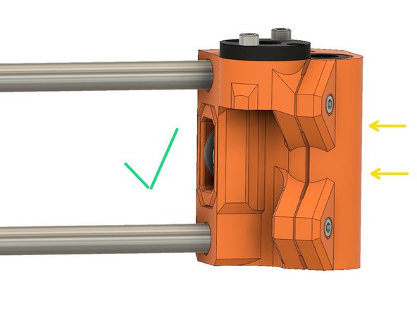
Adjust the two x_end_idler screws to to have the x_end_ilder_idle_mount flush as shown in the first image
-
Verify the x_end_idler_idler_mount adjustment, should not be like on second and third image.
-
-
-
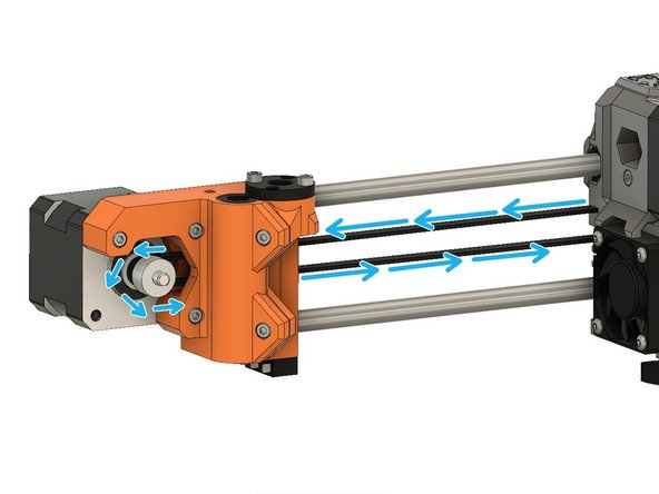
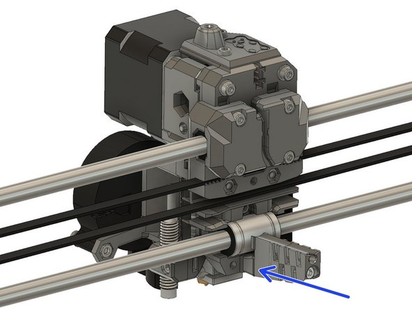
Slide one end of the 2GT timing belt into the right side of the x_carriage.
-
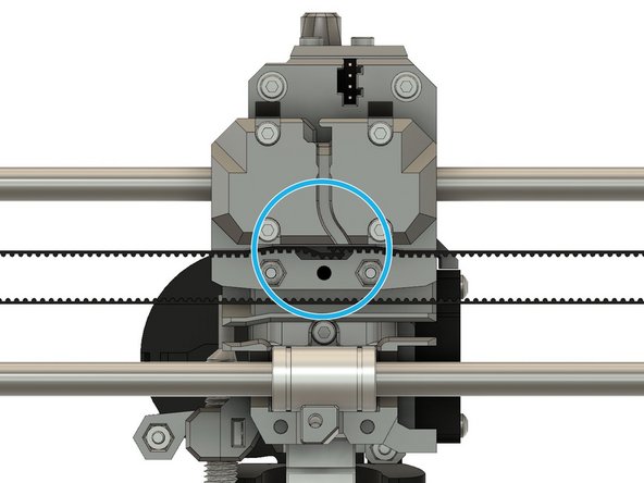
Verify that the belt is completely pressed into the slot and that it extends to the central portion.
-
Route the timing belt through the x_end_motor, around the pulley and back out through the x_end_motor.
-
-
-
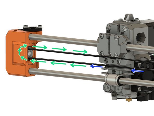
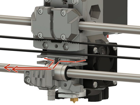
Route the timing belt through the x_carriage.
-
Continue to route the timing belt around the idler of the x_end_ilder_idler_mount and go back in the direction of the x_carriage.
-
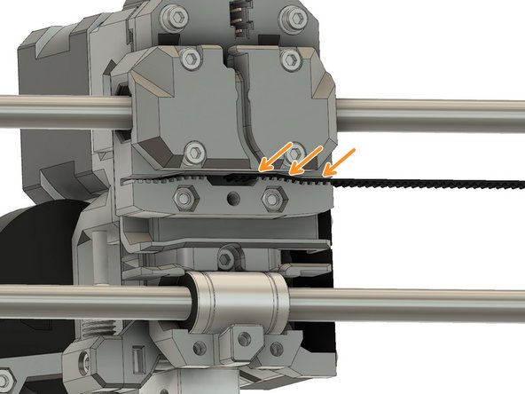
To finish routing the timing belt, attach few belt teeth in the x_carriage.
-
The belt should have almost no tension, it will be adjusted later.
-
Estimate the length and cut the belt. Finish to insert it in the x_carriage
-
Verify that the belt is completely pressed into the slot and that it extends to the central portion.
-
Verify that no cable is pinched by the belt.
-
-
-
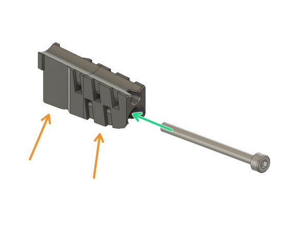
Join cable_guide_back_a and cable_guide_back_b together
-
Slide a M3x40 screw through them
-
Screw the M3x40 into the x_carriage
-
-
-
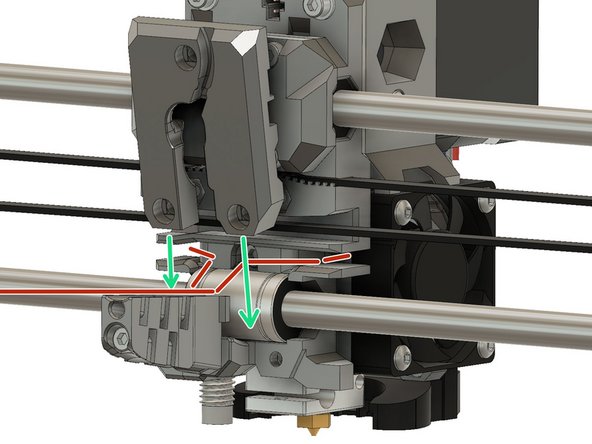
Create a bundle with the following cables: extruder motor, hotend fan, Pinda, and nozzle fan. Route the bundle as shown in the first image
-
Slide down the x_carriage_back with the cable bundle in the middle.
-
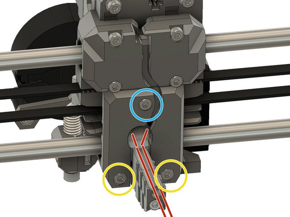
Secure the x_carriage_back bottom with one M3x18 screw
-
And two M3x10
-
-
-
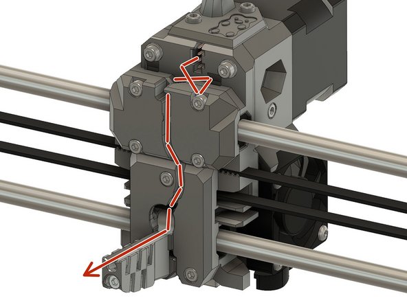
Clip the filament sensor cables on the filament sensor connector. The white wire of the cable should face up when connected to the filament sensor.
-
Route the filament sensor cable through the channel in the x_carriage_back.
-
-
-
These instructions are made for spiral wrap, but can be applied to textile sleeve without an issue.
-
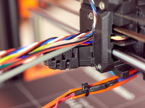
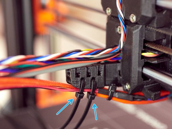
Using two zip ties, attach the hotend cables.
-
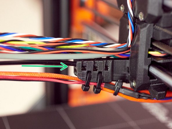
Insert the 3 mm nylon filament into the end of the cable_guide_back.
-
The nylon filament should slide in at least 10 mm. If you have trouble inserting it, the nylon filament end may be tapered. by a diagonal cut.
-
-
-
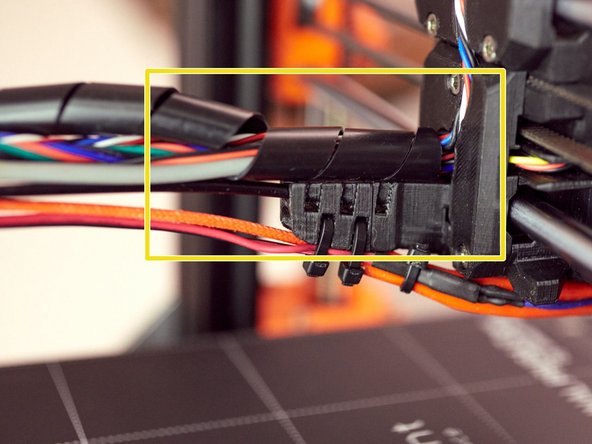
Wrap the wires coming out of the x_carriage_back using spiral wrap for 2-3 turns. The wrap should touch the x_carriage_back.
-
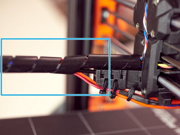
Continue spiral wrapping the cable now including the nylon filament and hotend cables.
-
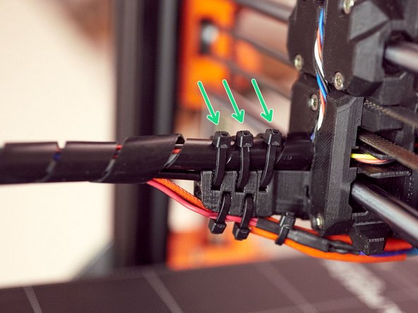
Secure the spiral wrap to the cable_guide_back using three zip ties.
-
Verify that no cable has been pinched.
-
-
-
Finish to wrap the spiral up to the Rambo Mini / Einsy.
-
Follow the original Prusa manual to connect your extruder cables on the Rambo Mini / Einsy:
-
-
-
-
-
-
Congratulations you have finished this chapter :-)
-
Go to the next chapter: 5. Final adjustments and calibration
-


Cancel: I did not complete this guide.
One other person completed this guide.
