-
-
Prepare the following parts:
-
4x y_end_caps
-
8x M4x5 set screws
-
Engage 2x M4x5 set screws into each of the y_end_caps, on the side with the 2 holes, until they are flush, as shown.
-
Sometimes, you may hear a "squeaking" noise, while screwing the set screw in. Insert the shorter side of the hex key, into the socket, to get more leverage, to reduce this.
-
Place one y_end_caps in each of the 4 corners of the Y axis frame. Make sure you orientate them correctly: the single mounting point must be on top.
-
Tighten each of the 8 grub screws to secure the y_end_caps in place.
-
-
-
Prepare the following parts:
-
2x z_end_caps
-
4x M4x5 set screws
-
Engage 2x M4x5 set screws into each of the z_end_caps until they are flush, as shown.
-
Install the z_end_caps on the exposed ends of the Z axis extrusions. Make sure you orientate them correctly
-
Tighten each of the 4x set screws to secure the z_end_caps in place.
-
-
-
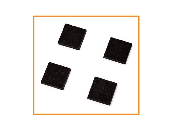
Prepare the 4 felt pads.
-
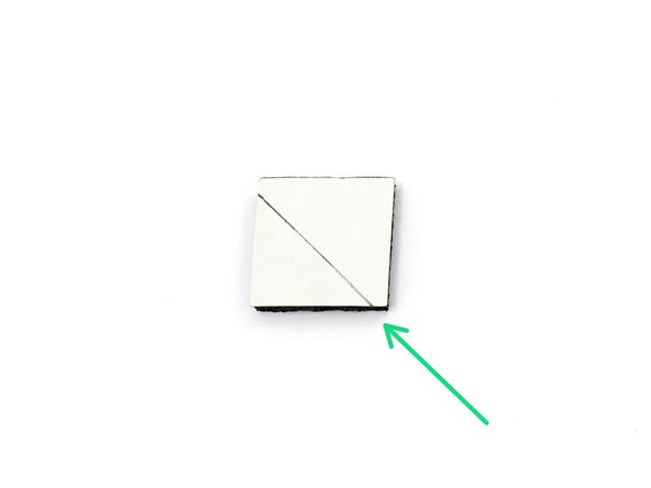
In order to remove the feet easily for maintenance, we are going to keep a non-sticky part.
-
Draw a line as shown in the image.
-
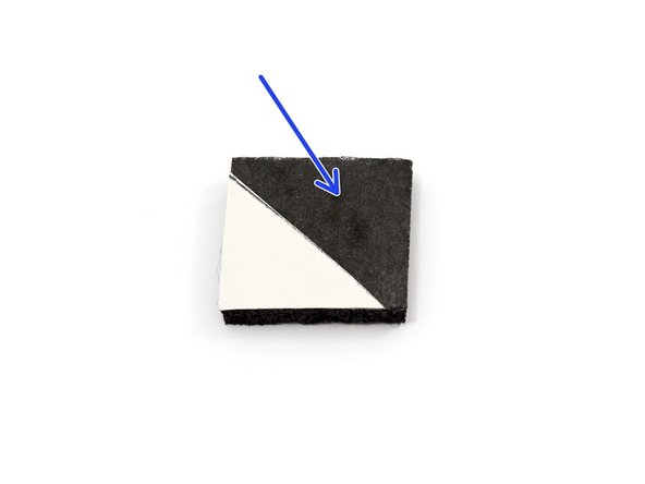
With pair of scisor, cut the protection on the line and remove the biggest section.
-
-
-
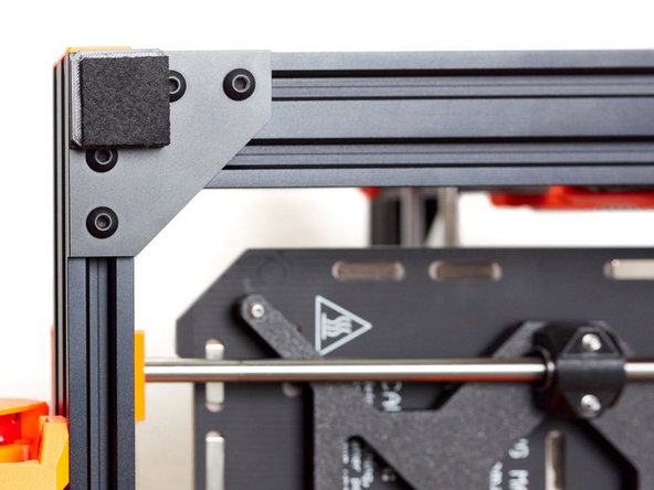
Stick the felt pads on the feet. Orientate them to have the protection on top of the screw.
-
-
-
Now we will set the Y axis belt tension.
-
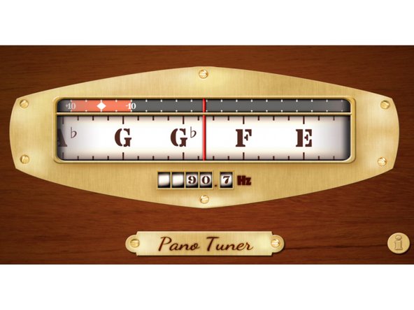
To accurately and consistently set the Y belt tension, we will make the belt vibrate to make a sound (or note). We will then tune this sound (or note) to a particular frequency, just as you would when tuning a guitar (or other stringed instrument). To help us do this, we will use a smartphone application.
-
Download and install the Pano Tuner application (developed by Kaleloft LLC) on your smartphone.
-
-
-
Launch the Pano Tuner app and place your smartphone under the heated bed. Make sure there is no noise in the room that could disrupt the measurement (like a ceiling fan).
-
-
-
Move the Y carriage to the middle of the Y axis.
-
Pluck the lower portion of the belt to make a sound. Don't pluck it too hard as it might touch the y_belt_holder and distort the sound.
-
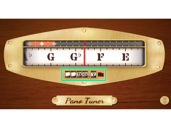
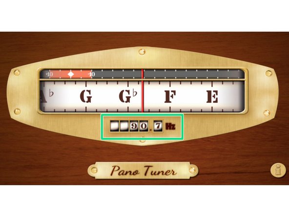
Adjust the belt tension until you have a frequency close to 90Hz (for a standard 6mm belt). Between each adjustment, move the heatbed back and forth along the whole length of the Y axis and then centre it again.
-
It is very important to move the heatbed between each measurement, this ensures that the belt is evenly tensioned.
-
If you are using our optional part for a 9mm belt, you then need to adjust the frequency to 80Hz.
-
If your belt is new, you can repeat this procedure after a few prints. A new belt will loosen in the first several hours of use.
-
-
-
Note that, in some of steps that follow, we are showing a BearExxa (Bear X axis and extruder). The steps are the same for the Prusa or Bondtech extruders.
-
Remove the steel sheet and place a sheet of paper on your heated bed (for protection). Remove any residual filament from the nozzle.
-
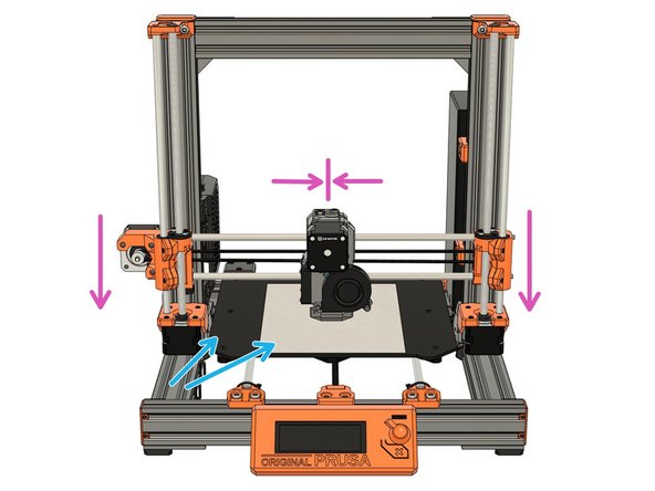
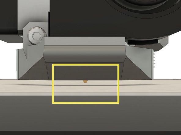
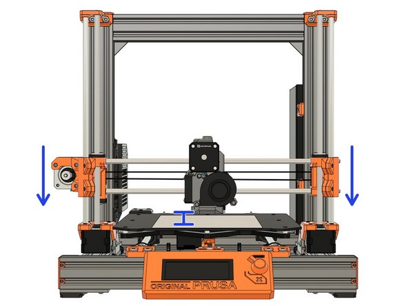
Center your extruder on the X axis. Move it down by rotating both Z lead screws simultaneously. Move the extruder down until the nozzle is just touching the paper.
-
Make sure the X axis is level (horizontal). When moving the extruder left and right, across the heated bed, the distance between the nozzle and heated bed should be the same. Adjust the Z lead screws, if required, until this is so.
-
Stop when the nozzle is just touching the paper.
-
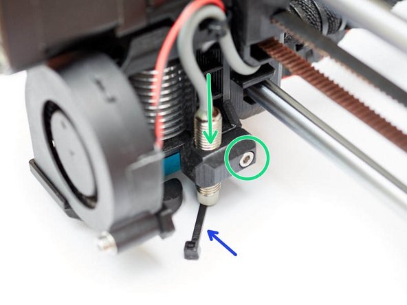
Place the middle section of a zip tie under the Pinda.
-
Loosen the M3x10 screw and gently move the PINDA down until it is touching the zip tie.
-
Tighten the M3x10 screw to secure the PINDA in place.
-
-
-
Plugin and turn on the printer.
-
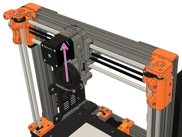
Using the screen menu, move the X axis up until it crashes in to the Z tops. The stepper motors will skip, making a noise - this will not damage the motors.
-
If, using the menu option, you are unable to raise the X axis to the Z tops, unplug the printer and plug it back in. You will now be able to reach the Z tops.
-
Using the screen menu, move the X axis down until the nozzle is approximately 10-15mm from the heated bed.
-
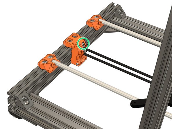
If you are using the Bear X axis (BearExxa, BearMera, Bondtech on Bear X axis) or the Original Prusa MK2(S)/MK2.5(S) X axis you need to release the tension on the X smooth rods by unscrewing the tensioning M3x10 screws a few turns. (Note! These are different to the Bear X axis belt tensioning screws.)
Hello, where in the assembly instructions are the two screws installed on the smooth rods? I've already assembled my X axis, just without these two set screws. Can I screw the two in afterwards? if so, how far do i have to screw it in? Regards
Hi @gregsaun in advance of the update to the guide, please can you quickly explain here how to install the X-axis smooth rod tensioning screws? I dont see anywhere for a captive nut, so are they supposed to self-tap into the printed material of the X end? Thanks!
Actually for tightening them I see that mentioned further down, though I didn’t find installing them.
Paul Arden - Resolved on Release Reply
I don’t actually find any place where the instructions talk about installing the X-axis smooth rod tensioning screws. The BearExxa guide shows them installed at some point but never seems tell you to install them. This guide and the Z-axis motion guide refer to loosening them but never to tightening them back up. Are they only installed when using the BearExxa X-axis on the original Prusa and not the bear upgrade perhaps?
Paul Arden - Resolved on Release Reply
-
-
-
Turn off the printer and move the extruder to the centre of the X axis.
-
Relax the tension of the X axis belt. Refer to the manual for your extruder if you are unsure how to do this. (Note! this was shown in step 06. Z axis motion.)
-
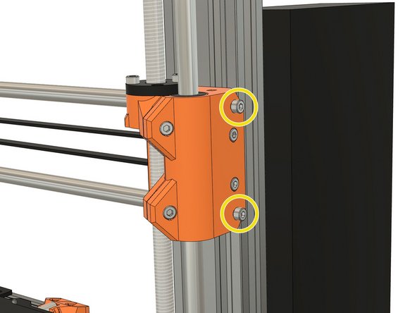
Loosen the screws which secure the trapezoidal nuts. This is to ensure that the Trapezoidal nuts 'self-centre' on the lead screws.
-
Make sure the trapezoidal nuts are able to move freely.
-
Alternating between all 4 screws, incrementally tighten each screw to secure the trapezoidal nuts (alternate between both sides during this process). Don't apply any lateral force to the trapezoidal nuts.
-
-
-
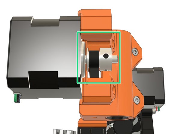
Verify that your X axis pulley is correctly aligned and not touching the X motor.
-
The belt tensioner location will vary, depending which X axis you are using.
-
Bear X axis (BearExxa, BearMera, Bondtech on Bear X axis): tensioner is on the right of the X axis (X end idler).
-
Original Prusa MK3(S) X axis: tensioner is on the X motor arm.
-
Original Prusa MK2(S)/MK2.5(S) X axis: there is no tensioner, you can only adjust the tension of the belt on the back of the extruder.
-
Grip the X motor shaft with pliers to prevent it rotating (grab the flat side of the shaft).
-
Tension the X axis belt. Do this while trying to move the extruder to the left or right. The belt should stay straight and should not bow up and skip over the drive pulley teeth.
-
No need to be very precise with the belt tension here as the final tension will be improved later (unless you have MK2(S)/MK2.5(S) X axis).
-
-
-
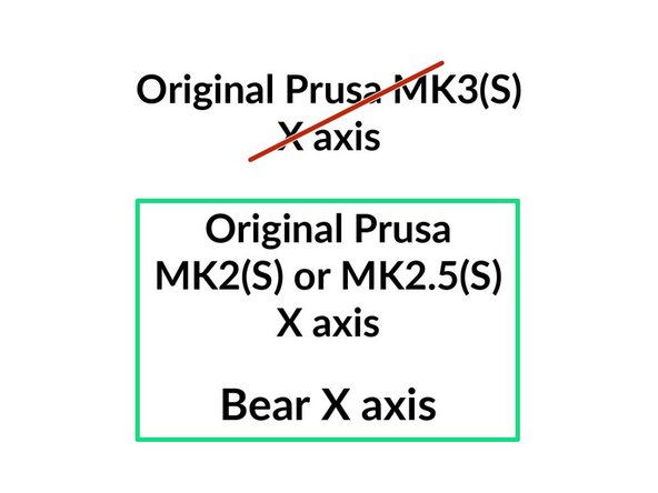
The next step is only if you use the Bear X axis or the Original Prusa MK2(S)/MK2.5(S) X axis.
-
Bear X axis includes: BearExxa, BearMera and Bondtech extruder on Bear X axis.
-
If you are using the Original Prusa MK3(S) X axis go directly to step 13.
-
-
-
Not all X axes have the exact same length due to manufacturing tolerances (this includes Original Prusa printers). This step will adjust your X axis length.
-
The 1st image shows what happens when you tension the X axis belt. We want to have the X ends as parallel as possible to the frame (or it will affect the X belt motion). (Note! the amount of deflection is exaggerated for illustrative purposes.)
-
1st image, top left: when the X axis is too short.
-
1st image, bottom left: when the X axis is too long.
-
1st image, right: when the X axis is the perfect length.
-
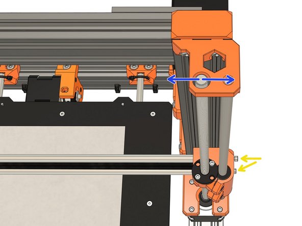
To adjust the length of the X axis we use the two M3x10 screws of the x_end_idler while looking at the Z tops.
-
While you tighten the M3x10 screws keep an eye on the Z tops. The M3x10 screws will move the Z lead screws laterally (left or right), adjust them so that the Z lead screws are centred.
-
Note that the M3x10 screws will not move the lead screws forwards or backwards, only laterally.
10mm screws bareley engage my rods and it looks like pushing on them at all might be too much. I think maybe there needs to be a printed “gage block” or similar tool to use here as it is a fairly large gap we are trying to make parallel.
You should have almost 1mm of adjustment, if you cannot reach them maybe your smooth rods are too short or frame assembly too large.
-
-
-
This step is for all types of X axis. However, you may not be able to be as precise when using an original Prusa axis.
-
Launch the Pano Tuner app and place your smartphone on the heated bed. Make sure there is no noise in the room that could disrupt the measurement (like a ceiling fan).
-
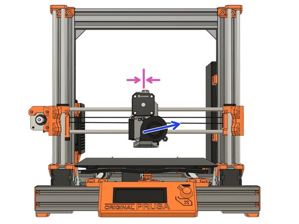
Move the extruder to the middle of the X axis.
-
Pluck the lower portion of the belt to make a sound. Don't pluck it too hard as it might touch the x carriage and distort the sound.
-
Adjust the belt tension until you have a frequency close to 90Hz. Between each adjustment, move the extruder all the way to the left and right and then centre it again.
-
It is very important to move the extruder between each measurement, this ensures that the belt is evenly tensioned.
-
If your belt is new, you can repeat this procedure after a few prints. A new belt will loosen in the first several hours of use.
Why X and Y frequencies are equal? X axis belt is longer than Y and must have lower frequency with same amount of tension, no?
What is a reasonable tolerance? I had trouble getting Y to better than +/- 1hz and X +/- 0.5hz.
-
-
-
We recommend that you flash the latest firmware to get the latest features and bug fixes.
-
The Bear frame is compatible with stock Prusa firmware, if you use an Original Prusa extruder. If you are using an alternative extruder you might need a different firmware:
-
Original Prusa extruder: you can use the original Prusa firmware available here.
-
BearExxa needs a custom firmware for calibration: read the guide here.
-
BearMera can use the Original Prusa firmware (or Bear calibration firmware) with some restrictions: read more in details here.
-
Bondtech extruder on stock X axis or Bear X axis needs a custom firmware: you can download it here.
-
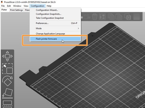
If you don't know how to flash the firmware to your original Prusa, check this guide: https://help.prusa3d.com/en/guide/upgrad...
-
-
-
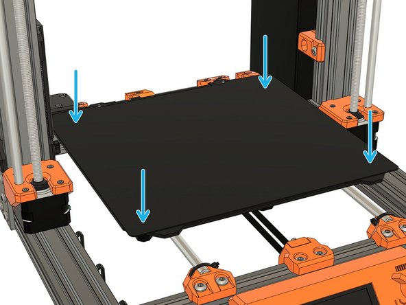
Place the steel sheet on the heated bed, if you are running a MK2.5(S) or MK3(S).
-
Verify that the heated bed is clean.
-
For MK2.5(S) and MK3(S), verify that nothing is between the steel sheet and heated bed.
-
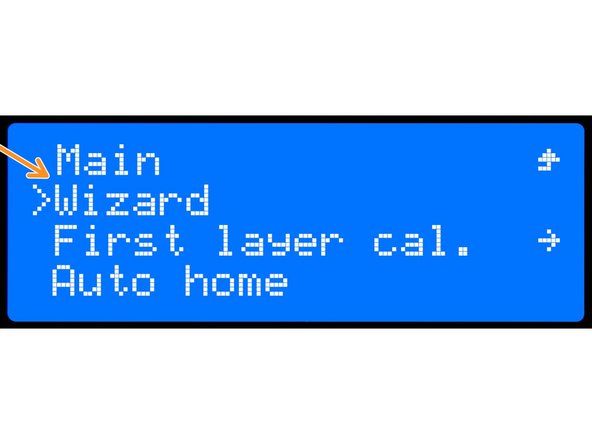
To check everything has been wired correctly and to calibrate the printer you need to run the wizard.
-
LCD Menu -> Calibration -> Wizard
-
If errors occur during the selftest, please fix them before going further.
-
Follow the instructions displayed on the LCD screen.
-
-
-
If you have installed a new extruder we recommend to calibrate the hotend PID. Otherwise you can skip this step.
-
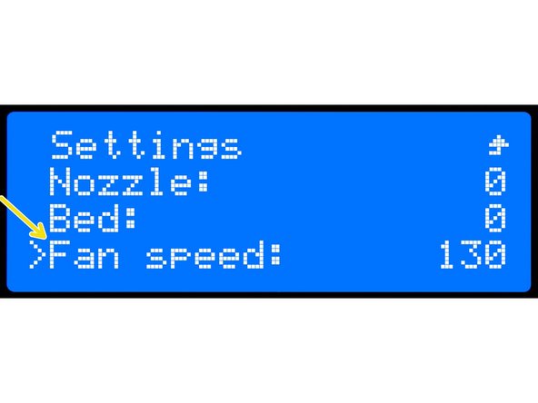
In Settings -> Temperature -> Fan speed set the value that corresponds to your most used slicer profile (min value = 0, max value = 255). For example, set it to 130 if you print mostly PETG and 255 if you print mostly PLA.
-
This is a little trick to make the PID calibration more reliable.
-
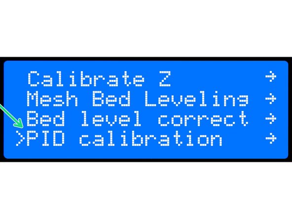
Run a PID calibration by selecting, Calibration -> PID calibration, from the menu.
-
Choose a temperature that matches your most commonly used printing temperature.
-
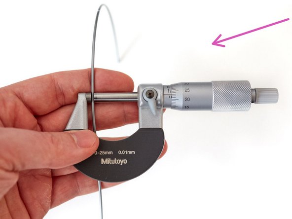
With a new extruder you will need to recalibrate your extrusion multiplier (per spool). Follow our guide here: 8. Extrusion multiplier and filament diameter
-
-
-
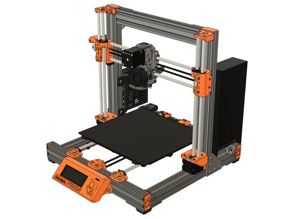
Congratulations, you have finished! You can now relax and enjoy your new frame.
-
Do you need a spool holder? Check our selection of optional parts made by the community.
-
Happy printing :)
-
Cancel: I did not complete this guide.
15 other people completed this guide.
5 Comments
Great guide! Thank you! However, after running everything, I'm getting an XYZ calibration failure. Specifically on the Z calibration step of it, step 2/4 it can't find the bed calibration point. Exact error message: "XYZ Calibration failed. Bed calibration point was not found." Set-up: Full Bear upgrade but with Original Prusa i3 MK3S+ parts and extruder. Any advice would be much appreciated. Thank you!
Hi, the instruction are too good and they are crisp. can I get the cad model of the final printer assembly
yashwanth vudathu - Resolved on Release Reply
I have 6 pieces of smaller yellow foils left, which I don't know where they will come from?
I don't know what are those. Could you share me a picture via discord, twitter or GitHub?




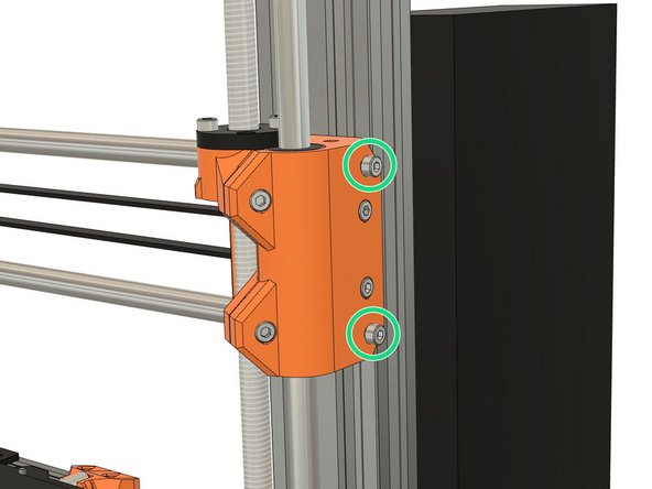
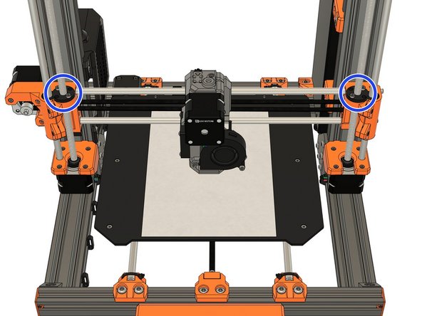
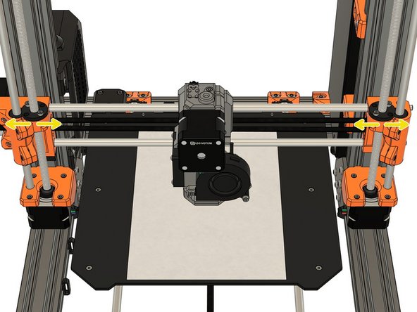
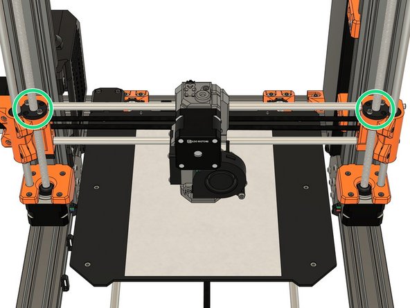



The bolts look to me M5, at least according to the hole size.
Additionally, there is 'set screw' here and 'grub screw' at the Step 2 - these are the same thing, aren't these (only UK/US naming)?
Ferenc Harmati - Resolved on Release Reply
Yes same things, I will update to have the same naming everywhere. They are M4.
Grégoire Saunier -