
-
-
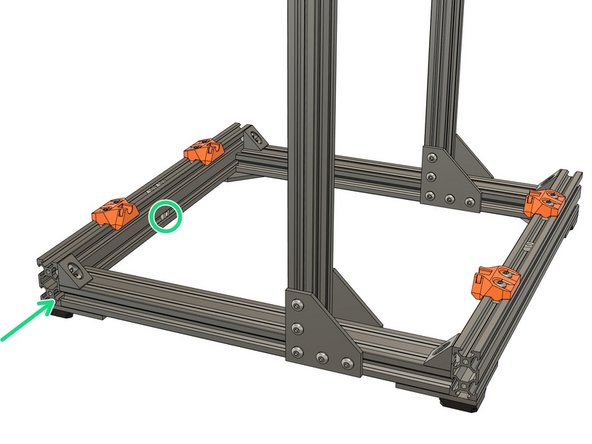
Slide 6x t-nuts in the top channel of the front extrusion.
-
Slide 5x t-nuts in the top channel of the rear extrusion.
-
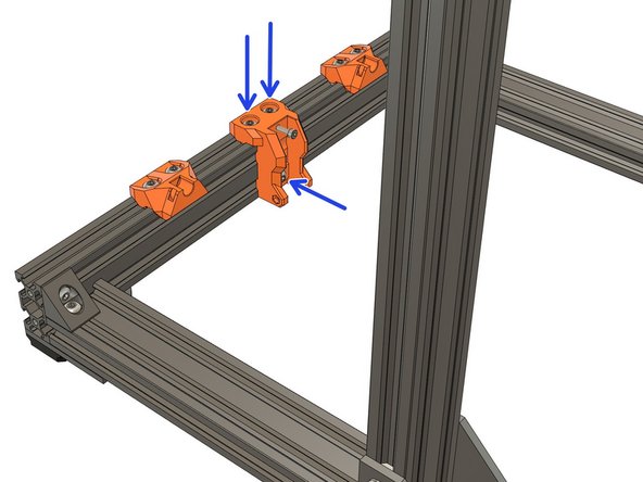
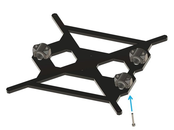
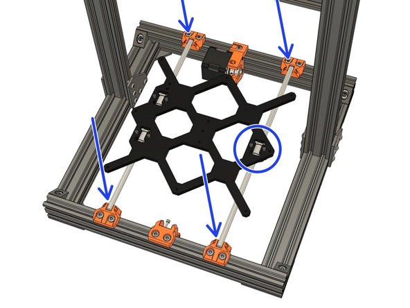
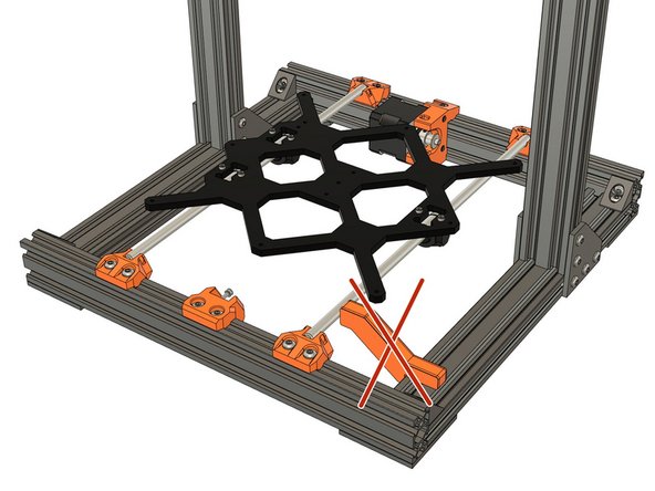
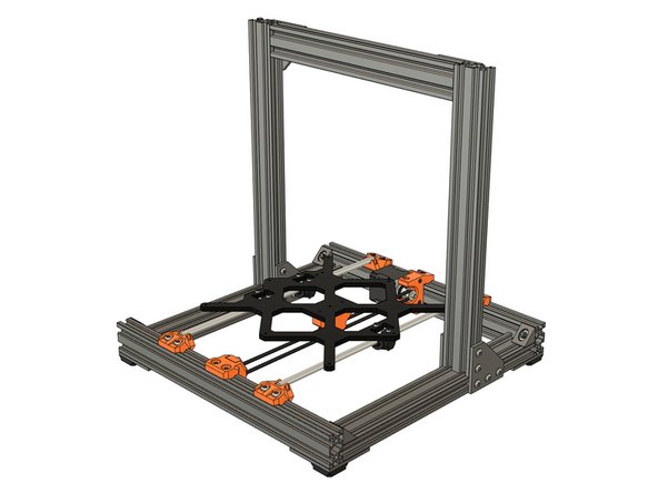
Attach 4x y_rod_holders to the frame, using 8x M5x12 screws, as shown. Tighten them just enough to prevent sliding, we will set the correct position later.
-
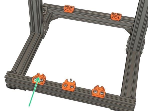
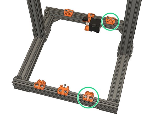
Check that you have have 2x free t-nuts in the top middle of the front extrusion and 1x free t-nut in the top middle of the rear extrusion.
-
-
-
Take the "y_idler_mount"
-
Place 1x M3 locknut in the pocket at the back of the part, as shown. Ensure sure the locknut has been fully inserted (use an Allen key or screwdriver) and is correctly oriented.
-
Thread 1x M3x25 screw through the front top hole and into the locknut. This will prevent you losing the locknut during the next steps.
-
I you have trouble to thread the screw you can remove the M3 nylock. Then take the M3x25 screw and thread the M3 nylock all the way through. Then remove it from the screw and repeat this assembly. This will make it slightly easier to screw in.
-
-
-
Slide 1x t-nut in the lower channel of the front extrusion, as shown.
-
Using 3x M5x10 screws, assemble the y_idler_mount. Tighten them just enough to prevent the part from sliding. We will set the correct position later.
-
Do not fully tighten the part to the frame. We will adjust its final position when we align the belt path with the bed and motor.
-
-
-
Take your time with this step, it could affect the alignment of the heatbed later.
-
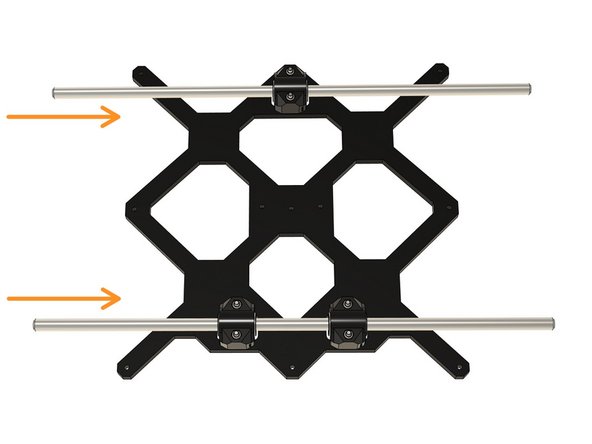
Clip 1x Y smooth rod (330mm long) into the y-rod holders, on the left-hand side.
-
Loosen the 4x M5x12 screws so that the y_rod_holders move easily.
-
Using the y_build_helper, adjust the position of the front y_rod_holder. Once the alignment is correct, fully tighten the M5x12 screws.
-
Make sure the y_build_helper is correctly seated against the extrusion and is in contact with the smooth rod.
-
Using the same y_build_helper, adjust and tighten the rear y-rod holder.
-
Carefully check the alignment of the front and rear of the smooth rods. You may need to repeat the adjustment to get them perfectly aligned.
-
-
-
Remove the Y smooth rod you installed in the previous step.
-
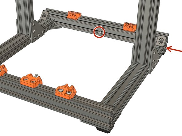
Slide 1x t-nut into the lower channel of the rear extrusion, as shown.
-
Be careful that this this t-nut does not fall out during the following steps. (Remember the tape / Blu Tack tip)
-
-
-
We are now going to prepare a few parts that will be used later in this chapter. Let's start with the Y bearing holders.
-
If you come from an Original Prusa MK3S+ you can reuse the black metal bearing clip instead of the printed ones and skip this step and the next one.
-
Take the 3x y_bearing_holder and insert 2x locknuts in each of them, 6x locknuts in total (reused from your Original Prusa). Those locknuts need to be reused from your Original Prusa printer.
-
We need to make sure that the locknuts are fully inserted in their pocket. To do this, take 1x M3x18 screw and 1x washer.
-
For each locknut in the y_belt_holders, insert the screw and tighten it against the washer, until the locknut is fully seated.
-
Remove the screw and washer and repeat for the 5 other locknuts of the bearing holders.
-
Make sure the 6x locknuts are fully seated in the bearing holders.
-
-
-
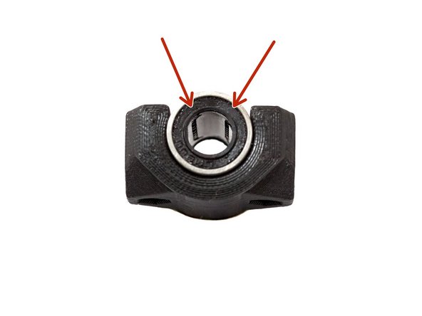
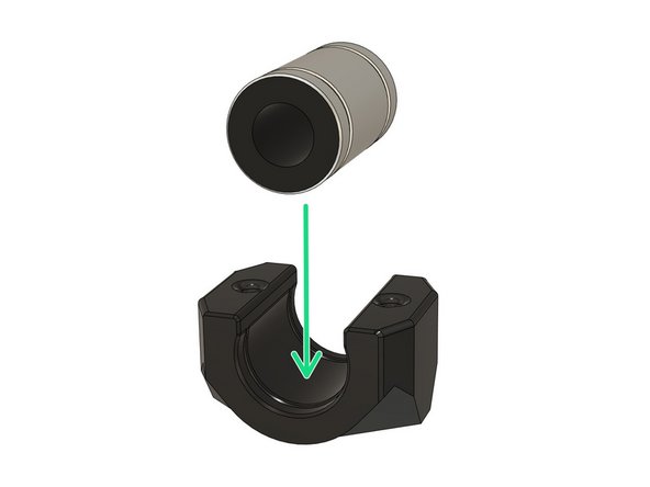
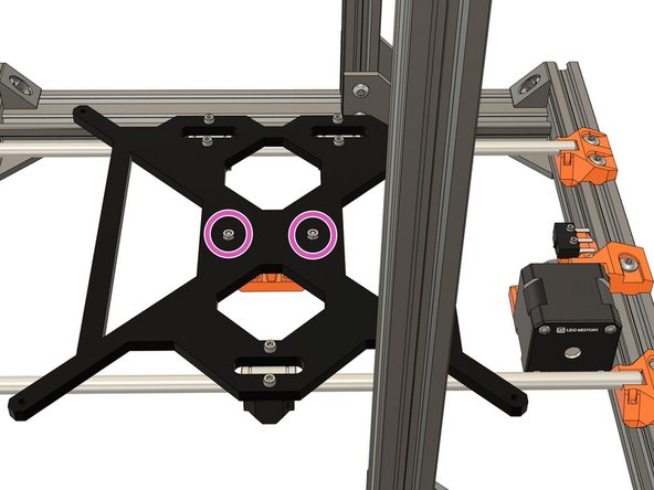
We are now going to insert the LM8UU bearings in the 3x y_bearing_holders. When you place the bearings you need to ensure that the rows of ball bearings are at 45° as shown in the image.
-
Insert the LM8UU bearings in the each of the 3x y_bearing_holders. Each bearing should be centred in the bearing holder. There are ridges in the plastic part which will align with the grooves in the LM8UU bearing.
-
Confirm that each bearing is aligned vertically as shown in the first image. It is very important to have all x3 bearings correctly aligned!
-
Keep the 3x y_bearing_holders ready for use later in this chapter.
-
-
-
The part you use in this step, might look different to that shown in the instructions, depending on which Prusa variant you are building. However, the following instructions are the same for each variant.
-
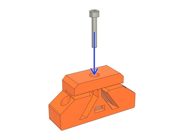
Insert 1x square nut into the y_belt_holder, as shown.
-
Thread in an M3x18 screw, from the top. Do not tighten it yet.
-
Keep the y_belt_holder for later use.
-
-
-
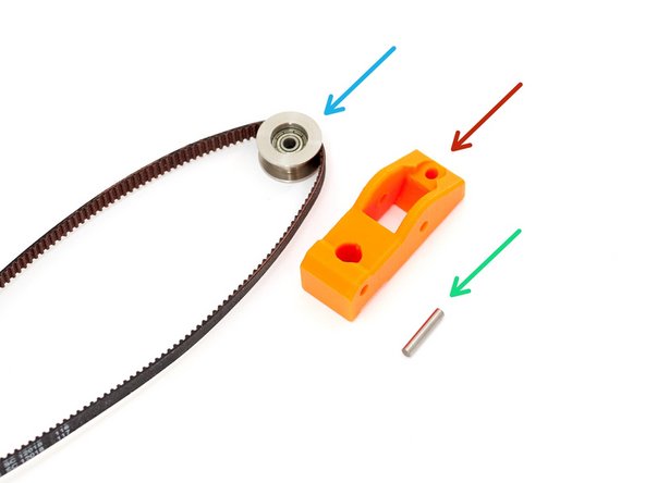
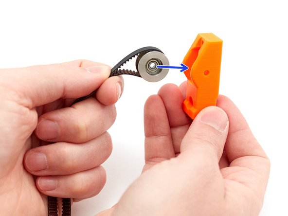
Prepare the following parts:
-
1x 20T idler with Y axis belt (650mm) looped around it.
-
1x y_idler_tensioner printed part.
-
1x dowel pin.
-
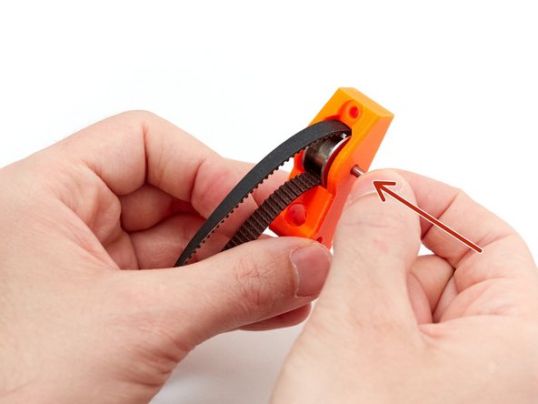
Place the belt around the idler and insert it into the y_idler_tensioner.
-
Insert the dowel pin from the right side. Make sure the dowel pin is fully inserted and does not stick out of the y_idler_tensioner
-
Keep the y_idler_tensioner for use later.
-
-
-
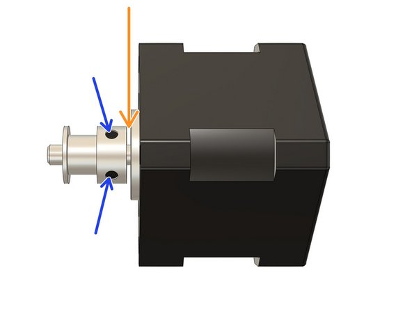
Take the Y axis motor.
-
Slide the 16T drive pulley on to the motor shaft, as shown. Make sure the pulley is not touching the motor (around 1mm of space between the motor body and drive pulley is enough).
-
Make sure the grub screws are both tight, ensuring that one of the grub screws is tightened against the flat part of the shaft.
-
Keep the Y motor for later use.
-
-
-
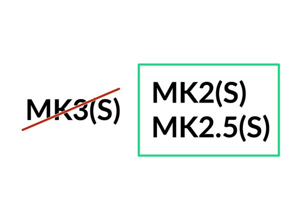
The next steps are for MK2(S) or MK2.5(S) printers only.
-
If you have MK3(S) jump to step 26.
-
-
-
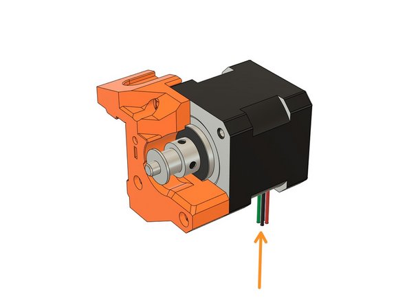
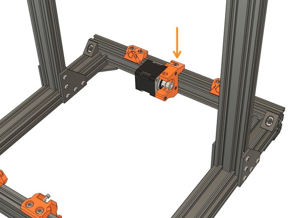
Place the Y motor on the y_motor_mount as shown in the first image. The cables must be orientated downward.
-
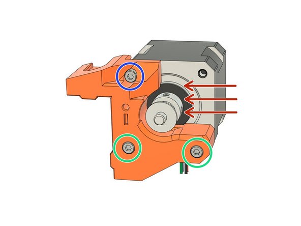
Secure the motor with the following screws. Do not fully tighten them yet.
-
2x M3x18
-
1x M3x10
-
Whilst pushing in the direction shown, fully tighten all 3 screws.
-
Check that the motor cables are oriented correctly.
-
-
-
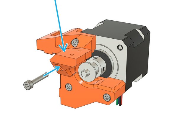
Place the y_motor_endstop_mount, as shown, and secure it with 1x M3x18 screw.
-
Place the Y end stop on the y_motor_endstop_mount with the switch actuator aligned with the notch, as shown.
-
Make sure the orientation of the switch is correct!
-
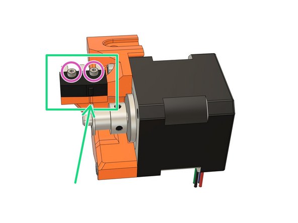
Insert and tighten 2x M2x12 screws to secure the end stop. Do not over tighten these screws, otherwise you may damage the end stop.
-
If it is too hard to tighten the M2 screws into the end stop mount, you may use a 1.5mm drill bit to clear the holes. Be careful that you do not break the drill bit.
-
-
-
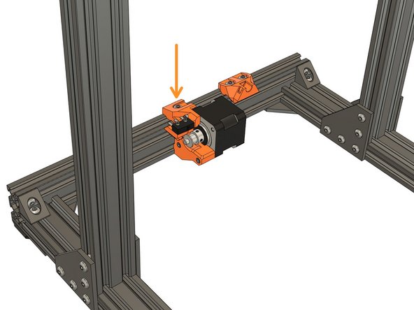
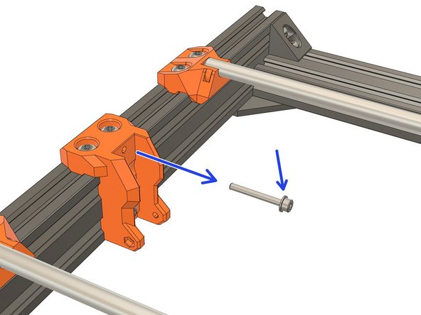
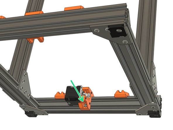
Install the y_motor_mount on the extrusions in the back. Do not fully tighten the screws. We will set the position in Step 19.
-
1x M5x12 on top
-
1x M5x16 on bottom
-
Always tighten the y_motor_mount screws evenly, incrementally and in turn. This ensures that the motor mount is properly square on the extrusions.
-
-
-
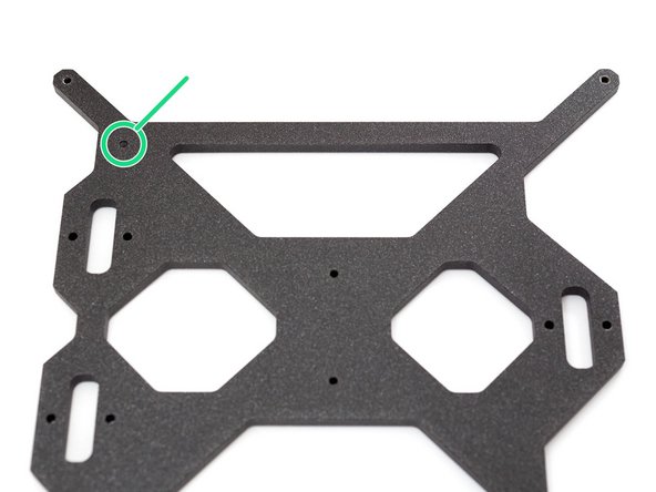
Locate the marker of the Y carriage.
-
Flip the carriage to have the marker facing the table (not visible anymore in the 2nd and 3rd image).
-
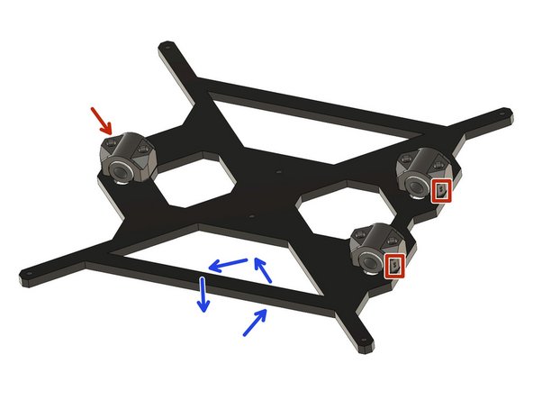
The y_bearing_holders have 2 dots printed on one of their corners. Place the 3x y_bearing_holders with the dots oriented as shown on the 2nd image.
-
Double check the orientation of the y_bearing_holders, this is important as you might have issues later with the heated bed.
-
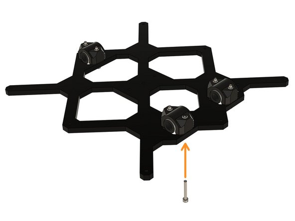
Secure the bearing holders with 6x M3x25 screws. Do NOT tighten them yet!
-
-
-
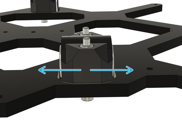
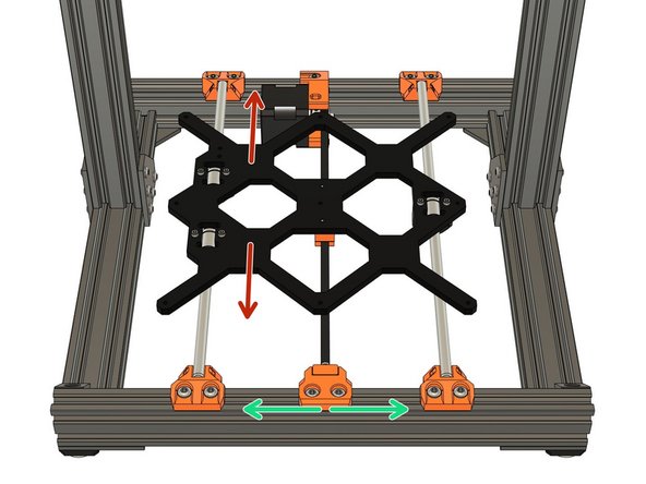
Take your time with this step. It is important that it is done correctly or it can cause issues later with your printer. Do not over-tighten the bearings or you may cause permanent damage to them.
-
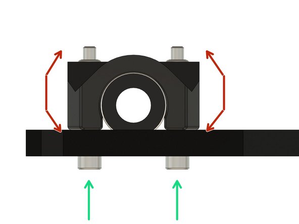
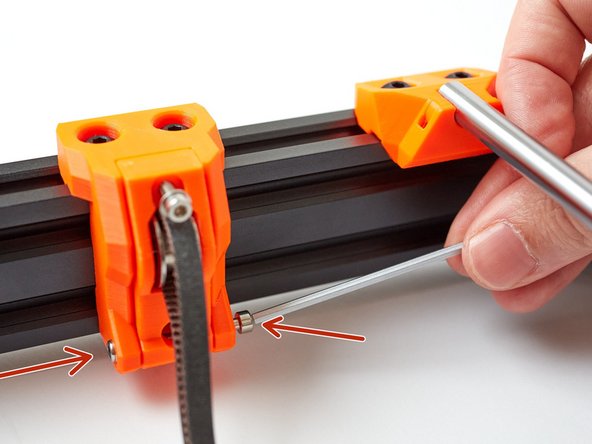
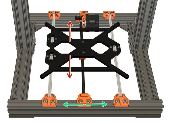
Start tightening evenly, incrementally and in turn. the M3x25 screws. While tightening, test if the bearing can rotate in the directions shown by the red arrows. When it no longer moves, in this direction, stop tightening immediately.
-
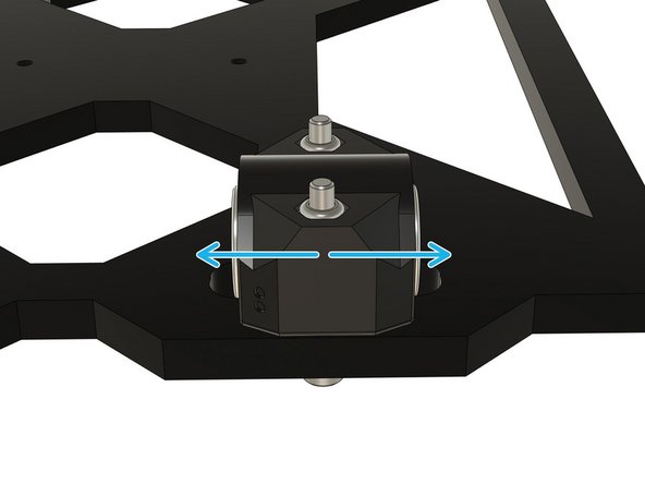
Check whether the bearings can slide along the slot.
-
If the bearing can slide: tighten evenly, incrementally and in turn, the M3x25 screws until you can't move it anymore. Do not over-tighten!
-
If the bearing is not moving anymore: continue to the next bearing.
-
Repeat this step for the two remaining bearings.
-
-
-
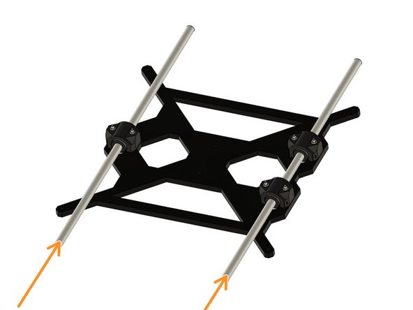
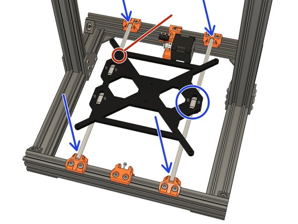
Gently insert 2x Y axis smooth rods (330mm long).
-
You must not use any significant force whilst inserting the rods into the linear bearings.
-
Don't rotate the smooth rods, the LM8UU bearings are not made to rotate.
-
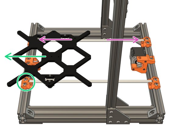
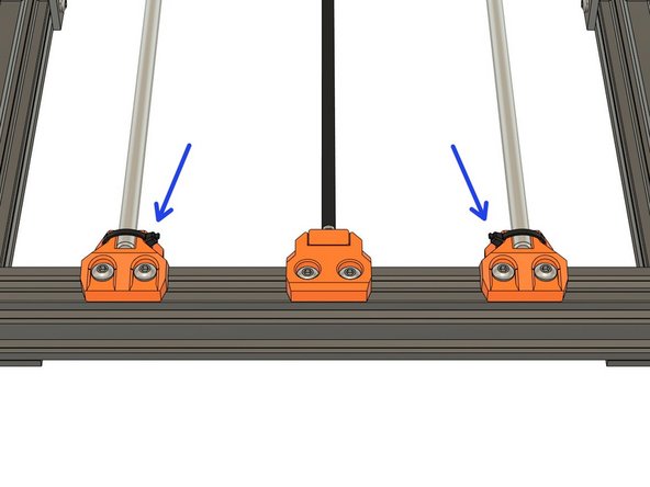
Loosen the M5 screws of the 2x right y_rod_holders. You should be able to slide them easily by hand.
-
Clip the Y smooth rods and carriage assembly into the y_rod_holders. The Single bearing should be to the right.
-
Verify the marker on the carriage is correctly positioned. If this is not the case, check that you have followed the previous steps correctly.
-
It is very important to have the LM8UU bearings correctly oriented as well as the marker or you will have issues later in the assembly.
-
-
-
Take your time with this step.
-
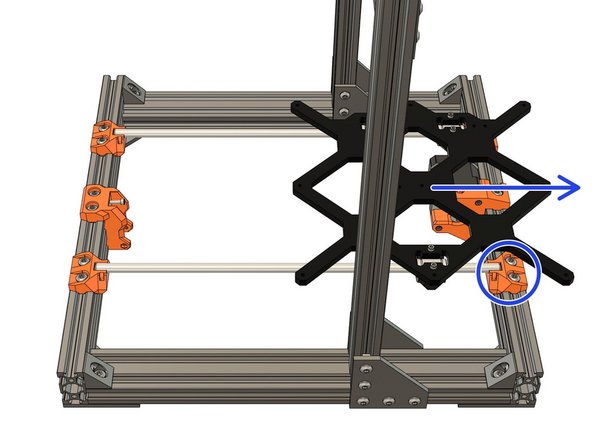
Move the Y carriage, backwards and forwards along the whole length of the Y axis, at least 6 times. This will align the right smooth rod (single LM8UU side).
-
Move the Y carriage to the front and tighten the screws for the right-front y_rod_holder evenly, incrementally and in turn.
-
Move the Y carriage to the back and tighten the screws for the right-back y_rod_holder evenly, incrementally and in turn.
-
Never use the build_helper_y with the right smooth rod, it is made to align left smooth rod only (dual LM8UU side).
-
Tech tip: If you have a 200mm caliper you can measure the distance from the smooth rods directly on the metal. The spacing of the smooth rods is 170mm, the diameter of smooth rods is 8mm, which means the external spacing you should measure will be 170 + 2*8/2 = 178mm.
-
-
-
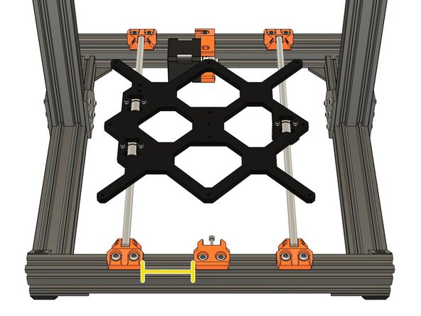
Set the y_idler_mount and y_motor_mount position as following:
-
47mm for the y_idler_mount.
-
61.5mm for the y_motor_mount.
-
We will adjust these positions, if necessary, after the belt is in place and tensioned.
-
-
-
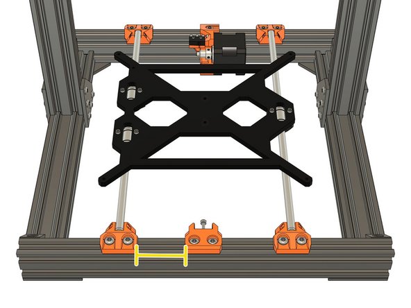
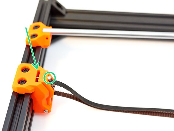
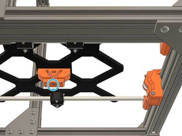
Install the y_belt_holder under the Y carriage. The grooves should face the single bearing side.
-
2x M3x12 (reused from your original Prusa).
-
2x M3 hex nut. Note that these nuts will be removed when installing the heated bed, they are only temporary.
-
Check the orientation of the y_belt_holder.
-
-
-
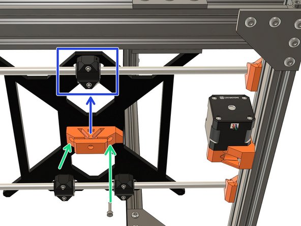
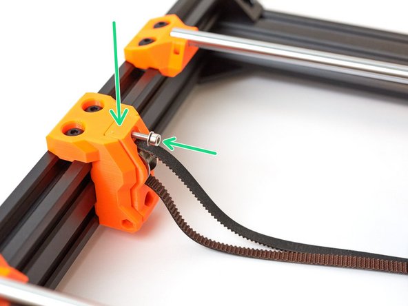
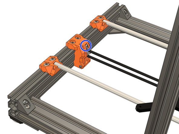
Remove the M3x25 screw, used during installation, from the y_idler_mount and add a washer to the screw.
-
Insert the y_idler_tensioner into the y_idler_mount and reinsert the M3x25 screw with its washer.
-
Insert an M3 locknut into the left side of the y_idler_mount and thread an M3x30 screw from the other side. Use this screw to help seat locknut correctly, in the part. Do not over-tighten this screw, the y_idler_tensioner should move with almost no resistance.
-
Confirm you have a washer on the M3x25 tensioning screw.
-
Check that the y_idler_tensioner can move with almost no resistance.
-
-
-
Unscrew the idler tensioner screw until there is a small gap (around 3mm).
-
Unscrew the clamp of the y_belt_holder to help the insertion of the belt in the next step.
-
-
-
Insert the top section of the belt into the left side of the y_belt_holder. If necessary, use a small slotted screwdriver to help insert the belt. The belt should be inserted to the full depth of the groove .
-
Make sure the belt teeth are correctly oriented according to the shape of the y_belt_holder.
-
Continue to route the belt around the Y motor pulley and finish by inserting the belt into the y_belt_holder. The belt should have almost no tension, it will be adjusted later.
-
If the belt is too long to fit inside the y_belt_holder you can trim the excess.
-
Verify that the belt is fully inserted into the slot.
-
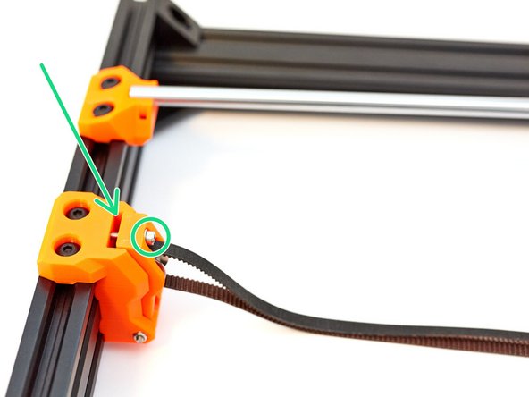
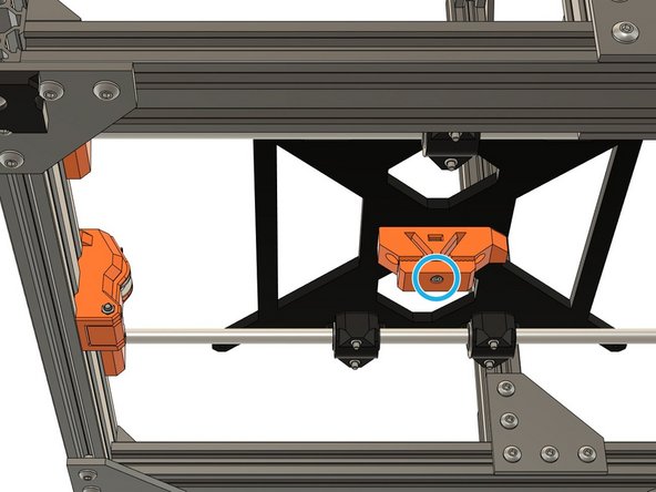
Tighten the M3x18 screw to secure the belt.
-
-
-
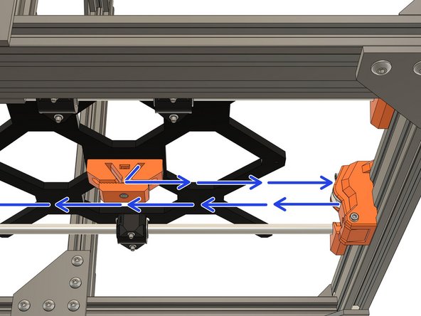
Apply a light tension to the belt to remove any slack. Do not over-tighten the belt or adjustments will be impossible.
-
We will adjust the belt, to the correct tension, in a later step.
-
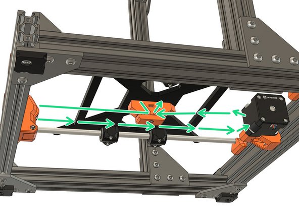
Adjust the position of y_idler_mount and y_motor_mount using their M5 screws. Try to have the belt riding centred as best as possible on the pulley (motor side) and the idler (tensioner side).
-
It is important to move the Y carriage back and forth along the whole axis between each adjustment.
-
Remember that when you tighten the y_idler_mount and y_motor_mount screws you must do so evenly, incrementally and in turn. If you don't do this you may cause those parts to be misaligned.
-
-
-
Secure the Y smooth rods with 4 zip ties. Note the orientation of them.
-
-
-
Congratulations you have finished this chapter :)
-
Go to the next chapter: 06. Z axis motion
-
-
-
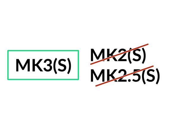
The next steps are for MK3(S) only until the end of this chapter.
-
If you are building a MK2(S) or MK2.5(S) jump to step 38.
-
-
-
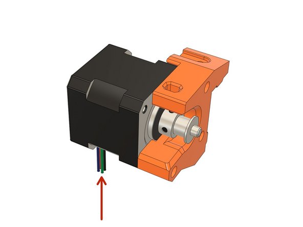
Place the Y motor on the y_motor_mount as shown on the first image. The cables must be orientated downward.
-
Secure the motor with 3x M3x18 screws. Do not fully tighten them yet.
-
Whilst pushing in the direction shown, fully tighten all 3 screws.
-
Check that the motor cables are oriented correctly.
-
-
-
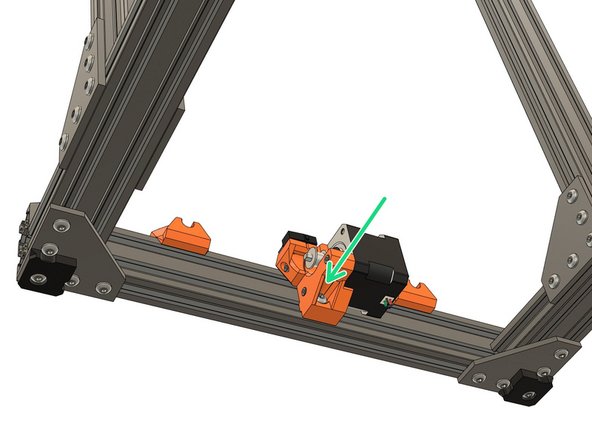
Install the y_motor_mount on the extrusions in the back. Do not fully tighten the screws. We will set the position in a later step.
-
1x M5x12 on top.
-
1x M5x16 on bottom.
-
Always tighten the y_motor_mount screws evenly, incrementally and in turn. This ensures that the motor mount is properly square on the extrusions.
-
-
-
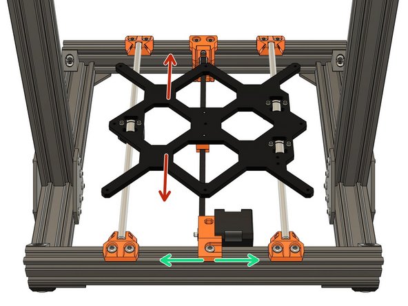
Take your time with this step. It is important that it is done correctly or it can cause issues later with your printer. Do not over-tighten the bearings or you may cause permanent damage to them.
-
Secure the bearing holders with 6x M3x25 screws. Do NOT tighten them yet!
-
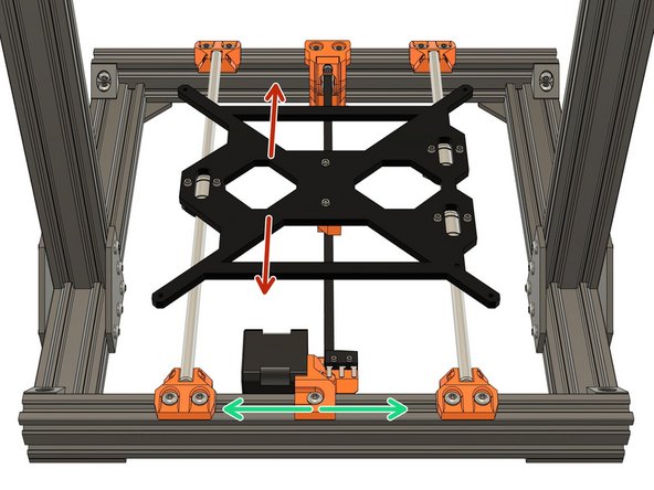
Start tightening, evenly, incrementally and in turn. the M3x25 screws. While tightening, test if the bearing holder can rotate in the directions shown by the red arrows. When it no longer moves, in this direction, stop tightening immediately.
-
Check whether the bearings can slide along the slot.
-
If the bearing can slide: tighten evenly, incrementally and in turn, the M3x25 screws until you can't move it anymore. Do not over-tighten!
-
If the bearing is not moving anymore: continue to the next bearing.
-
Repeat this step for the two remaining bearings.
-
-
-
Gently insert 2x Y axis smooth rods (330mm long).
-
You must not use any significant force whilst inserting the rods into the linear bearings.
-
Don't rotate the smooth rods, the LM8UU bearings are not made to rotate.
-
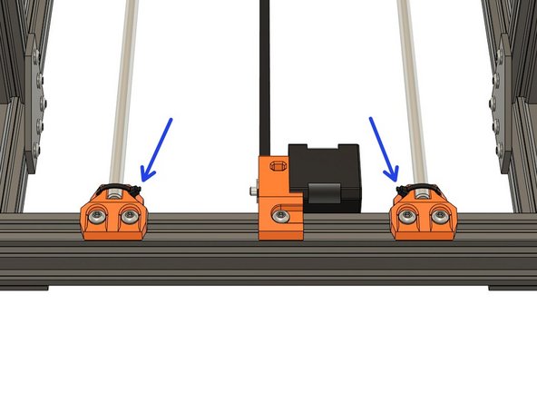
Loosen the M5 screws of the 2x right y_rod_holders. You should be able to slide them easily by hand.
-
Clip the Y smooth rods and carriage assembly into the y_rod_holders. The Single bearing should be to the right.
-
It is very important to have the LM8UU bearings correctly oriented or you will have issues later in the assembly.
-
-
-
Take your time with this step.
-
Move the Y carriage, backwards and forwards along the whole length of the Y axis, at least 6 times. This will align the right smooth rod (single LM8UU side).
-
Move the Y carriage to the front and tighten the right-front y_rod_holder incrementally.
-
Move the Y carriage to the back and tighten the screws for the right-back y_rod_holder evenly, incrementally and in turn.
-
Never use the build_helper_y with the right smooth rod, it is made to align left smooth rod only (dual LM8UU side).
-
Tech tip: If you have a 200mm caliper you can measure the distance from the smooth rods directly on the metal. The spacing of the smooth rods is 170mm, the diameter of smooth rods is 8mm, which means the external spacing you should measure will be 170 + 2*8/2 = 178mm.
-
-
-
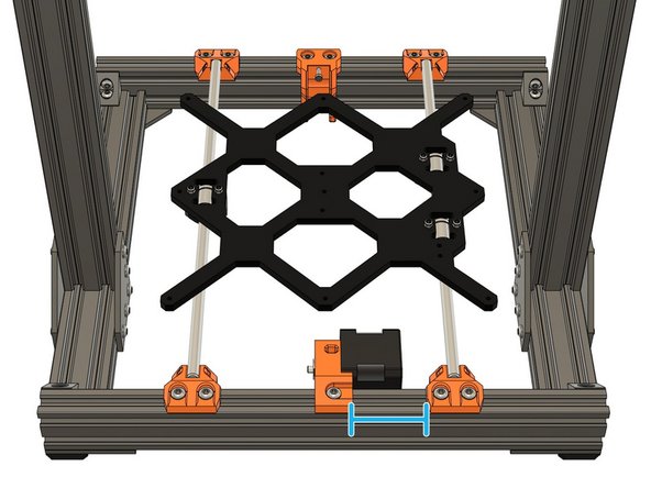
Set the y_idler_mount and y_motor_mount position as following:
-
51mm for the y_idler_mount.
-
48mm for the y_motor_mount.
-
We will adjust these positions, if necessary, after the belt is in place and tensioned.
-
-
-
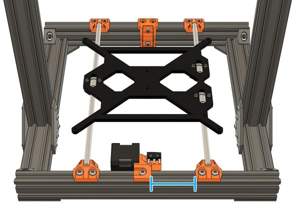
Install the y_belt_holder under the Y carriage with 2x M3x10 (reused from your original Prusa). The grooves should face the dual bearings side.
-
Verify the orientation of the y_belt_holder.
-
-
-
Remove the M3x25 screw, used during installation, from the y_idler_mount and add a washer to the screw.
-
Insert the y_idler_tensioner into the y_idler_mount and reinsert the M3x25 screw with its washer.
-
Insert an M3 locknut into the left side of the y_idler_mount and thread an M3x30 screw from the other side. Use this screw to help seat locknut correctly, in the part. Do not over-tighten this screw, the y_idler_tensioner should move with almost no resistance.
-
Confirm you have a washer on the M3x25 tensioning screw.
-
Check that the y_idler_tensioner can move with almost no resistance.
-
-
-
Unscrew the idler tensioner screw until there is a small gap (about 3mm).
-
Unscrew the clamp of the y_belt_holder to help the insertion of the belt in the next step.
-
-
-
Insert the top section of the belt into the left side of the y_belt_holder. If necessary, use a small slotted screwdriver to help insert the belt. The belt should be inserted to the full depth of the groove .
-
Make sure the belt teeth are correctly oriented according to the shape of the y_belt_holder.
-
Continue to route the belt around the Y motor pulley and finish by inserting the belt into the y_belt_holder. The belt should have almost no tension, it will be adjusted later.
-
If the belt is too long to fit inside the y_belt_holder you can trim the excess.
-
Verify that the belt is fully inserted into the slot.
-
Tighten the M3x18 screw to secure the belt.
-
-
-
Apply a light tension to the belt to remove any slack. Do not over-tighten the belt or adjustments will be impossible.
-
We will adjust the belt, to the correct tension, in a later step.
-
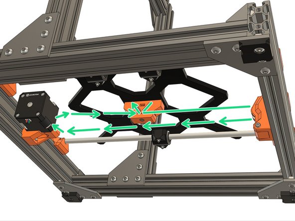
Adjust the position of y_idler_mount and y_motor_mount using their M5 screws. Try to have the belt riding centered as best as possible on the pulley (motor side) and the idler (tensioner side).
-
It is important to move the Y carriage back and forth along the whole axis between each adjustment.
-
Remember that when you tighten the y_idler_mount and y_motor_mount screws you must do so evenly, incrementally and in turn. If you don't do this you may cause those parts to be misaligned.
-
-
-
Secure the Y smooth rods with 4 zip ties. Note the orientation of them.
-
-
-
Congratulations you have finished this chapter :)
-
Go to the next chapter: 06. Z axis motion
-


Cancel: I did not complete this guide.
40 other people completed this guide.

2 Comments
@gregsaun I can translate the manual into Polish lang.
How can I do this and did you provide for this possibility.
Cyryl Sochacki - Resolved on Release Reply
Hi, thank you for proposing your help. Unfortunately, I don’t have time right now and to be honest I don’t know how it works with Dozuki